2009 MODU Code
2.2.1 Means of access
Paragraph 2.2.1.2
1 Some possible alternative means of access are listed under paragraph 3.9 of the
MODU Technical Provisions for means of access for inspection (MODU TP). Always
subject to acceptance as equivalent by the Administration, alternative means such as
an unmanned robot arm, ROVs with necessary equipment of the permanent means of
access for overall and close-up inspections and thickness measurements of the deck
head structure, such as deck transverses and deck longitudinals of ballast tanks and
other tanks, holds and other spaces where gas hazardous atmosphere may be present,
should be capable of:
2 When considering use of alternative means of access as addressed by paragraph 3.9
of the MODU TP, refer to IACS Recommendation No.91 "Guidelines for
Approval/Acceptance of Alternative Means of Access".
Paragraph 2.2.1.3
3 This interpretation is to be contained in a section of the Means of Access (MA)
Manual, as specified in the Revised technical provisions for means of access for
inspections (resolution MSC.158(78)).
2.2.2 Safe access to holds, tanks, ballast tanks and other spaces
4 This regulation is only applicable to integral tanks. Independent tanks can be
excluded. Additionally, spud cans and jack cases of self-elevating units can be
excluded.
5 The wording "not intended for the carriage of oil or hazardous materials" applies
only to "similar compartments", i.e. safe access can be through a pump-room, deep
cofferdam, pipe tunnel, cargo hold or double hull space.
Paragraph 2.2.2.2
6 A tank of less than 35 m in length without a swash bulkhead requires only one
access hatch.
7 Where rafting is indicated in the access manual as the means to gain ready access
to the under deck structure, the term
"similar obstructions" referred to in
the regulation includes internal structures (e.g. webs > 1.5 m deep) which restrict
the ability to raft (at the maximum water level needed for rafting of under deck
structure) directly to the nearest access ladder and hatchway to deck. When rafts or
boats alone, as an alternative means of access, are allowed, permanent means of
access should be provided to allow safe entry and exit. This means:
-
.1 access direct from the deck via a vertical ladder and small platform
fitted approximately 2 m below the deck in each bay; or
-
.2 access to deck from a longitudinal permanent platform having ladders
to deck in each end of the tank. The platform should, for the full
length of the tank, be arranged in level with, or above, the maximum
water level needed for rafting of under deck structure. For this
purpose, the ullage corresponding to the maximum water level should be
assumed not more than 3 m from the deck plate measured at the midspan of
deck transverses and in the middle length of the tank. A permanent means
of access from the longitudinal permanent platform to the water level
indicated above should be fitted in each bay (e.g. permanent rungs on
one of the deck webs inboard of the longitudinal permanent platform).
2.2.3 Access manual
8 The access manualfootnote is to address spaces listed in section 2.2.2 of the
Code. As a minimum, the English version should be provided.
9 The access manual should contain at least the following two parts:
-
Part 1: Plans, instructions and inventory required by paragraphs
.1.1 to .1.7 of section 2.2.3.1. This part is to be approved by the
Administration or the organization recognized by the Administration.
-
Part 2: Form of record of inspections and maintenance, and change
of inventory of portable equipment due to additions or replacement after
construction. This part is to be approved for its form only at new
building.
10 The following matters should be addressed in the access manual:
-
.1 the access manual should clearly cover scope as specified in the
regulations for use by crews, surveyors and port State control officers;
-
.2 approval / re-approval procedure for the manual, i.e. any changes of
the permanent, portable, movable or alternative means of access within
the scope of the regulation and the Technical provisions are subject to
review and approval by the Administration or by the organization
recognized by the Administration;
-
.3 verification of MA should be part of safety construction survey for
continued effectiveness of the MA in that space which is subject to the
statutory survey;
-
.4 inspection of MA by the crew and/or a competent inspector of the
company as a part of regular inspection and maintenance (see
interpretation for paragraph 2.2.1.3);
-
.5 actions to be taken if MA is found unsafe to use; and
-
.6 in case of use of portable equipment, plans showing the means of
access within each space indicating from where and how each area in the
space can be inspected.
Paragraph 2.2.3.2
11 Critical structural areas should be identified by advanced calculation techniques
for structural strength and fatigue performance, if available, and feedback from the
service history and design development of similar or sister units.
Revised technical provisions for
means of access for inspections (resolution
MSC.158(78))
1 Preamble
16 In the context of the above requirement, the deviation should be
applied only to distances between integrated PMA that are the subject of paragraph
2.1.2 of table 1.
17 Deviations should not be applied to the
distances governing the installation of underdeck longitudinal walkways and
dimensions that determine whether permanent access are required or not, such as
height of the spaces and height to elements of the structure (e.g. cross-ties).
3 Technical provisions
Paragraph 3.1
18 The permanent means of access to a
space can be credited for the permanent means of access for inspection.
Paragraphs 3.2 and 3.3
19 Sloping structures
are structures that are sloped by 5 or more degrees from horizontal plane when a
unit is in upright position at even-keel.
20 Guard rails should
be fitted on the open side. For stand-alone passageways guard rails should be fitted
on both sides of these structures.
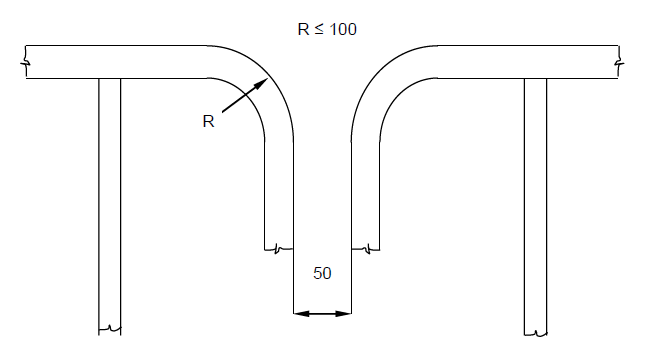
21 Discontinuous top handrails
are allowed, provided the gap does not exceed 50 mm.
22 The same
maximum gap is to be considered between the top handrail and other structural
members (i.e. bulkhead, web frame, etc.).
23 The maximum distance
between the adjacent stanchions across the handrail gaps should be 350 mm where the
top and mid handrails are not connected together and 550 mm when they are connected
together.
24 The maximum distance between the stanchion and other
structural members should not exceed 200 mm where the top and mid handrails are not
connected together and 300 mm when they are connected together.
25 When the top and mid handrails are connected by a bent rail, the outside radius
of the bent part should not exceed 100 mm (see figure below).
26 Non-skid construction is such that the surface on which personnel
walks provides sufficient friction to the sole of boots even if the surface is wet
and covered with thin sediment.
27 "Substantial construction" is
taken to refer to the designed strength as well as the residual strength during the
service life of the unit. Durability of passageways together with guard rails should
be ensured by the initial corrosion protection and inspection and maintenance during
services.
28 For guard rails, use of alternative materials such
as GRP should be subject to compatibility with the liquid carried in the tank.
Non-fire resistant materials should not be used for means of access to a space with
a view to securing an escape route at a high temperature.
29
Requirements for resting platforms placed between ladders are equivalent to those
applicable to elevated passageways.
Paragraph 3.4
30 Where the vertical manhole is at a height of more than 600 mm above
the walking level, it should be demonstrated that an injured person can be easily
evacuated.
Paragraph 3.6
31 Vertical
height of handrails should not be less than 890 mm from the centre of the step and
two course handrails are to be provided.
32 The requirement of
two square bars for treads specified in MODU TP, paragraph 3.6, is based upon the
specification of construction of ladders in paragraph 3(e) of annex 1 to resolution
A.272(VIII), which addresses inclined ladders. MODU TP, paragraph 3.4, allows for
single rungs fitted to vertical surfaces, which is considered for a safe grip. For
vertical ladders, when steel is used, the rungs are to be formed of single square
bars of not less than 22 mm by 22 mm for the sake of safe grip.
33 The width of inclined ladders for access to a hold should be at least 450 mm to
comply with the Australian AMSA Marine Orders Part 32, Appendix 17.
34 The width of inclined ladders other than an access to a hold should
not be less than 400 mm.
35 The minimum width of vertical
ladders should be 350 mm and the vertical distance between the rungs is to be equal
and should be between 250 mm and 350 mm.
36 A minimum climbing
clearance in width should be 600 mm other than the ladders placed between the hold
frames.
37 The vertical ladders should be secured at intervals
not exceeding 2.5 m apart to prevent vibration.
Paragraphs
3.7 to 3.9
38 A mechanical device such as hooks for
securing at the upper end of a ladder should be considered as an appropriate
securing device if a movement fore/aft and sideways can be prevented at the upper
end of the ladder.
Paragraphs 3.10 and 3.11
39 See
interpretation for paragraphs 2.2.4.1 and 2.2.4.2 of 2009 MODU Code (paragraphs 12 to 15 above).
Paragraphs 3.12 and 3.13
40 Either a vertical
or an inclined ladder or a combination of them may be used for access to a large
hold where the vertical distance is 6 m or less from the deck to the bottom of the
hold.
41 Adjacent sections of vertical ladder need to be
installed so that the following provisions are complied with (refer to figures A and
B):
-
- The minimum "lateral offset" between two adjacent sections
of vertical ladder, is the distance between the sections, upper and
lower, so that the adjacent stringers are spaced of at least 200 mm,
measured from half thickness of each stringer.
-
- Adjacent sections of vertical ladder should be installed
so that the upper end of the lower section is vertically overlapped, in
respect to the lower end of the upper section, to a height of 1500 mm in
order to permit a safe transfer between ladders.
-
- No section of the access ladder should be terminated
directly or partly above an access opening.
Paragraph 3.14
42 Deck is defined as
"weather deck".
Figure "A"
Vertical
Ladder – Ladder through the linking platform
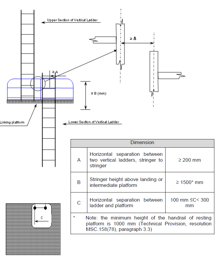
Figure "B"
Vertical Ladder – Side
mount
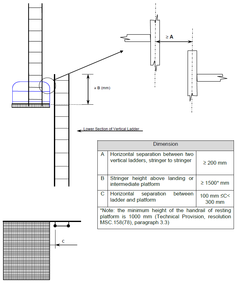
Table 1 – Means of access, paragraph 1.1
43
For tanks containing oil products other than crude oil (e.g. fuel oil, diesel oil,
base oil) where lower corrosion is expected, section 1.1 of table 1 should not be
applied. For tanks containing products considered corrosive (e.g. brine, drilling
mud), section 1.1 should be applied.
44 Sub-paragraphs .1 to .3
define access to underdeck structure, access to the uppermost sections of transverse
webs and connection between these structures.
45 Sub-paragraphs
.4 to .6 define access to vertical structures only and are linked to the presence of
transverse webs on longitudinal bulkheads.
46 If there are no
underdeck structures (deck longitudinals and deck transverses) but there are
vertical structures in the tank supporting transverse and longitudinal bulkheads,
access in accordance with sub-paragraphs .1 to .6 should be provided for inspection
of the upper parts of vertical structure on transverse and longitudinal bulkheads.
47 If there is no structure in the tank, section 1.1 of table 1
should not be applied.
48 The vertical distance below the
overhead structure should be measured from the underside of the main deck plating to
the top of the platform of the means of access at a given location.
49 The height of the tank should be measured at each tank. For a tank
the height of which varies at different bays, item 1.1 should be applied to such
bays of a tank that have height 6 m and over.
Table 1 – Means
of access, paragraph 1.1.2
50 There is need to provide
continuous longitudinal permanent means of access when the deck longitudinals and
deck transverses are fitted on deck but supporting brackets are fitted under the
deck.
Table 1 – Means of access, paragraph 1.1.3
51 Means of access to tanks may be used for access to the permanent
means of access for inspection.
Table 1 – Means of access,
paragraph 1.1.4
52 The permanent fittings required to
serve alternative means of access, such as wire lift platform, that are to be used
by crew and surveyors for inspection should provide at least an equal level of
safety as the permanent means of access stated by the same paragraph. These means of
access should be carried on board the unit and be readily available for use without
the filling of water in the tank.
53 Therefore, rafting should
not be acceptable under this provision.
54 Alternative means of
access should be part of the Access Manual which is to be approved on behalf of the
flag State.
Table 1 – Means of access paragraph 2.1
55 Paragraph 2.1.1 represents requirements for access to
underdeck structures, while paragraph 2.1.2 is a requirement for access for survey
and inspection of vertical structures on longitudinal bulkheads (transverse webs).
Table 1 – Means of access, paragraph 2.1.1
56 For a tank, the vertical distance between horizontal upper stringer
and deck head of which varies at different sections, item 2.1.1 should be applied to
such sections that fall under the criteria.
57 The continuous
permanent means of access may be a wide longitudinal, which provides access to
critical details on the opposite side by means of platforms as necessary on web
frames. In case the vertical opening of the web frame is located in way of the open
part between the wide longitudinal and the longitudinal on the opposite side,
platforms should be provided on both sides of the web frames to allow safe passage
through the web frame.
58 Where two access hatches are required
by the 2009 MODU Code, paragraph 2.2.2.2, access ladders at each
end of the tank should lead to the deck.
Table 1 – Means of
access, paragraph 2.1.2
59 The continuous permanent means
of access may be a wide longitudinal, which provides access to critical details on
the opposite side by means of platforms as necessary on web frames. In case the
vertical opening of the web is located in way of the open part between the wide
longitudinal and the longitudinal on the opposite side, platforms should be provided
on both sides of the web to allow safe passage through the web.
60 A "reasonable deviation", as noted in MODU TP, paragraph 1.4, of not more than
10% may be applied where the permanent means of access is integral with the
structure itself.
Table 1 – Means of access, paragraph 2.2
61 Permanent means of access between the longitudinal
continuous permanent means of access and the bottom of the space should be provided.
62 The height of a bilge hopper tank located outside of the
parallel part of the unit should be taken as the maximum of the clear vertical
distance measured from the bottom plating to the hopper plating of the tank.
63 The foremost and aftmost bilge hopper ballast tanks with raised
bottom, of which the height is 6 m and over, a combination of transverse and
vertical MA for access to the upper knuckle point for each transverse web should be
accepted in place of the longitudinal permanent means of access.
Table 1 – Means of access, paragraph 3.1
64 Means of
access should be provided to the crossdeck structures of the foremost and aftermost
part of the each hold.
65 Interconnected means of access under
the cross deck for access to three locations at both sides and in the vicinity of
the centreline should be acceptable as the three means of access.
66 Permanent means of access fitted at three separate locations accessible
independently, one at each side and one in the vicinity of the centreline, should be
acceptable.
67 Special attention should be paid to the structural
strength where any access opening is provided in the main deck or cross deck.
Table 1 – Means of access, paragraph 3.3
68
Particular attention should be paid to preserve the structural strength in way of
access opening provided in the main deck or cross deck.
Table
1 – Means of access, paragraph 3.4
69 The movable means
of access to the underdeck structure of cross deck need not necessarily be carried
on board the unit. It is sufficient if it is made available when
needed.