5.3.1.1
Workstation Area
The workstations for navigating and manoeuvring, monitoring
and for the bridge wings should be planned, designed and placed within
an area spacious enough for not less than two operators, but close
enough for the workstations to be operated by one person.
5.3.1.2
Single Operator Console
Width for Seated Operations
The console should be dimensioned and configured so that all
relevant controls can be reached from a sitting position.
5.3.1.3
Left-to-Right Viewing
Angle
The console should be designed that from the normal working
position the total required left-to-right viewing angle should not
exceed 190°. This angle shall be reduced whenever possible through
appropriate control-display layout.
5.3.1.4
Console Height
The top of the consoles should not exceed a height of 1200 mm.
5.3.1.5
Console Leg Room
The upper leg room of the console should have a minimum of 450
mm in depth and the lower leg room a minimum of 600 mm in depth.
5.3.1.6
Chart Table Dimensions
The chart table should be large enough to accommodate all chart
sizes normally used internationally for navigation.
5.3.1.7
Chair Design
Chairs at workstations designed for a sitting position should
be capable of rotating with the foot rest being arrested, adjustable
in height, and capable of being arrested on the floor. Chairs should
be movable out of the operating area.
5.3.2
Device, Control and Display
Integration
5.3.2.1
Logical Arrangement
The devices, displays and controls should be fitted in a logical
arrangement and combined into function groups.
5.3.2.2
Location Consistency
Location of recurring functional groups and individual items
should be similar from console to console.
5.3.2.3
Visual Information
for more than one User
Displays providing visual information to more than one person
on duty should be located for easy viewing by all users concurrently,
or if this is not possible, the displays should be duplicated.
5.3.2.4
Control and Display
Location
Controls and their associated displays should be located so
that the information on the displays can be easily read, during the
operation of the controls.
5.3.2.5
Simultaneous Use
A visual display that must be monitored concurrently with manipulation
of a related control should be located so that the operator is not
required to observe the display from an extreme visual angle and thus
introduce the possibility of parallax error.
5.3.2.6
Control/Indicator Discernability
Controls or combined controls/indicators should be visually
and tactually distinguishable from elements which only indicate.
5.3.2.7
High Priority Displays
Where two operators must use the same display, and the displays
have high priority duplicate sets should be provided whenever there
is adequate space. Otherwise, displays should be centred between the
operators, alternatively they can be placed that they can be easily
monitored by both operators, e.g., above the front window.
5.3.2.8
Centring of Shared
Displays
Where two operators must use the same display, and secondary
displays must be shared, they should be centred between the operators
if they are equally important to each operator. If the displays are
more important to one operator than to the other, they should be placed
nearest the operator having the principal requirements for using them,
alternatively they can be placed so that they can be easily monitored
by both operators, e.g., above the front window.
5.3.3
Arrangement and Grouping
of Controls
5.3.3.1
Control Placement
Controls requiring frequent or accurate settings should not
be placed more than 675 mm from the front edge of the console.
5.3.3.2
Control Positioning
for Simultaneous Operation
Controls should be located so that simultaneous operation of
two controls will not necessitate a crossing or interchanging of hands.
5.3.3.3
Location of Primary
and Frequently Used Controls
The most important and frequently used controls should have
the most favourable position with respect to ease of reaching and
grasping (particularly rotary controls and those requiring fine settings),
e.g., keys for emergency functions should have a prominent position.
5.3.3.4
Consistent Arrangement
The arrangement of functionally similar or identical controls
should be consistent from workstation to workstation, panel to panel
throughout the bridge.
5.3.3.5
Spacing Between Controls
Appropriate spacing between the controls should be provided.
5.3.4
Display Arrangement
5.3.4.1
Immediate Field of
View
The most important and/or frequently used displays should be
located within the operator's immediate field of view (viewing area
with eye rotation only) (Fig. 5.1).
5.3.4.2
Preferred Viewing
Area
The preferred viewing area should be reserved exclusively for
the most important and/or frequently used displays (Fig. 5.1).
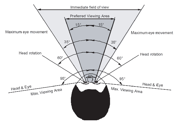
Figure 5.1 Horizontal field of view
5.3.5
Labelling of Controls
and Displays
5.3.5.1
Functional Labelling
Controls and displays should be labelled clearly and unequivocally
according to their function, possibly by using standardized symbols.
5.3.5.2
Label Terminology
The selection and use of terminology for labels should be consistent
between controls and displays.
5.3.6
Lighting of Devices
5.3.6.1
Adjustable Lighting
Adjustable lighting (dimming control) should be provided for
controls and visual displays, including display, control, and panel
labels and critical markings, that must be read at night or under
darkened conditions. The range of the dimming control should permit
the displays to be legible under all ambient illumination conditions.
5.3.6.2
Dimming Capabilities
The lighting of the devices should be continuously or multiple
step adjustable down to zero, except the lighting of warning and alarm
indicators and the control of the dimmers which should remain readable.
5.3.6.3
Individual Lighting
Adjustment
Each device should be fitted with an individual lighting adjustment.
In addition functional groups of devices, displays and controls should
be equipped with common light adjustment.