REGULATION II-2/9 – CONTAINMENT OF FIRE
Tables 9.5 and 9.6:
1 Decks and bulkheads
Decks and bulkheads to be insulated to "A-30" fire integrity are those
boundaries of single spaces protected by their own fire-extinguishing system.
2 Hatches
Class "A" fire integrity respectively does not apply to hatches fitted on
open deck adjacent to ro-ro/vehicle spaces and on decks separating ro-ro/vehicle spaces,
provided that such hatches are constructed of steel.
3 Access doors
"A-0" fire integrity does not apply to access doors to ro-ro/vehicle spaces
fitted on open decks, provided that such access doors are constructed of steel.
4 Movable ramps
Movable ramps installed on decks referred to in Interpretation1 above which
form boundaries of "A-30" fire integrity shall be constructed of steel and shall be
insulated to "A-30" fire integrity, except for the "working parts" of such movable ramps
(e.g. hydraulic cylinders, associated pipes/accessories) and members supporting such
fittings which do not contribute to the structural strength of the boundary. Such
movable ramps need not be subject to fire test. This is applicable to non-watertight
doors used for loading/unloading of vehicles.
5 Ventilation ducts
Where ducts for a ro-ro/vehicle spaces pass through other ro-ro/vehicle
spaces without serving those spaces, each duct shall be insulated all along itself to
"A-30" fire integrity in ways of other ro-ro/vehicle spaces unless the sleeves and fire
dampers in compliance with SOLAS regulation II-2/9.7.3.1 in order to prevent spread of
fire through the ducts are fitted.
6 Ventilators
"A-0" fire integrity does not apply to ventilators constructed of steel
fitted on open decks adjacent to ro-ro/vehicle spaces.
REGULATION II-2/13 – MEANS OF ESCAPE
Regulations 13.3.3.2 and 13.3.3.3
The "Lowest open deck" should be a category (10) "Open deck" (as defined in
SOLAS chapter II-2, regulations 9.2.3.3.2.2 and 9.2.4.2.2.2) at the lowest height from
baseline in way of accommodation spaces.
Regulations 13.4.1.4, 13.4.1.6, 13.4.2.5 and 13.4.2.6
1 Main workshop
A "main workshop" means a compartment enclosed on at least three sides by bulkheads or
gratings, usually containing welding equipment, metal working machinery and workbenches.
2 Machinery control rooms
A "machinery control room" means a space which serves for control and/or monitoring of
machinery used for ship's main propulsion.
3 Continuous fire shelter
A "continuous fire shelter" means a route from a main workshop, or from a
machinery control room, which allows safe escape, without entering the machinery space,
to a location outside the machinery space. Such a continuous fire shelter need not be a
protected enclosure as envisaged by SOLAS regulation II-2/13.4.1.1 or II-2/13.4.2.1.1.
The boundaries of the continuous fire shelter shall be at least "A-0" class divisions
and be protected by self-closing "A-0" class doors. The continuous fire shelter shall
have minimum internal dimensions of at least 800 mm x 800 mm for vertical trunks and 600
mm in width for horizontal trunks, and shall have emergency lighting provisions. The
figures below represent typical arrangements of the continuous fire shelters through
trunks or through spaces/rooms to a location outside the machinery space, which should
be considered as effective.

Figure 1 – Single room escape via trunk
|

Figure 2 – Single room escape via protected enclosure
|

Figure 3 – Room to room escape via trunk
|
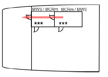
Figure 4 – Room to room direct escape
|

Figure 5 – Room to room escape via other space/room
|
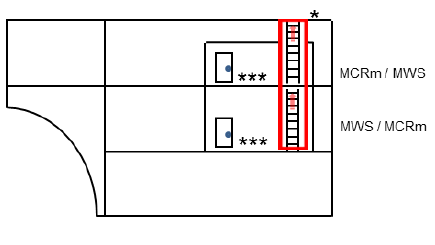
Figure 6 – Room to room escape via trunk (different
decks)
|
MCRm: Machinery
Control Room
MWS: Main Workshop
|
* Vertical trunk
(minimum dimensions: 800 mm x 800 mm) enclosing ladders or stairways to
be at least "A-0" class divisions and to be protected by self-closing
"A-0" class doors
** Horizontal trunk (minimum width:
600 mm) to be at least "A-0" class divisions and to be protected by
self-closing "A-0" class doors
*** Fire integrity not
required
|
Regulation 13.4.1
1 A "safe position" can be any space, excluding lockers and storerooms
irrespective of their area, cargo spaces and spaces where flammable liquids are stowed,
but including special category spaces and ro-ro spaces, from which access is provided
and maintained clear of obstacles to the embarkation decks (regulations II-2/13.4.1.1.1
and 13.4.1.4).
2 Inclined ladders/stairways in machinery spaces being part of, or providing
access to, escape routes but not located within a protected enclosure should not have an
inclination greater than 60° and should not be less than 600 mm in clear width. Such
requirement need not be applied to ladders/stairways not forming part of an escape
route, only provided for access to equipment or components, or similar areas, from one
of the main platforms or deck levels within such spaces (regulation II-2/13.4.1).
3 Machinery spaces may include working platforms and passageways, or
intermediate decks at more than one deck level. In such case, the lower part of the
space should be regarded as the lowest deck level, platform or passageway within the
space. At deck levels, other than the lowest one, where only one means of escape other
than the protected enclosure is provided, self-closing fire doors should be fitted in
the protected enclosure at that deck level. Smaller working platforms in-between deck
levels, or only for access to equipment or components, need not be provided with two
means of escape (regulation II-2/13.4.1.1).
4 A protected enclosure providing escape from machinery spaces to an open
deck may be fitted with a hatch as means of egress from the enclosure to the open deck.
The hatch should have minimum internal dimensions of 800 mm x 800 mm (regulation
II-2/13.4.1.1.1).
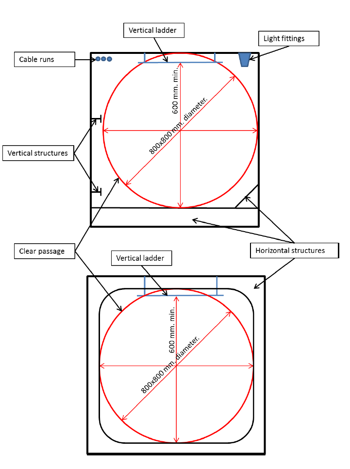
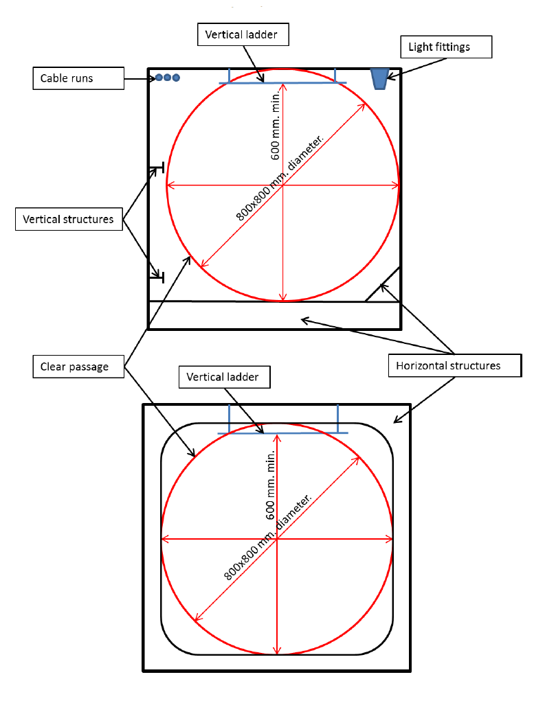
5 Internal dimensions should be interpreted as clear width, so that a
passage having diameter of 800 mm is available throughout the vertical enclosure, as
shown in figure 7, clear of ship's structure, with insulation and equipment, if any. The
ladder within the enclosure can be included in the internal dimensions of the enclosure.
When protected enclosures include horizontal portions their clear width should not be
less than 600 mm. Figure 7 is given as example of some possible arrangements which may
be in line with the above interpretation (regulation II-2/13.4.1.1.1).
Figure 7
Regulation 13.4.2
1 A "safe position" can be any space, excluding cargo spaces, lockers and
storerooms irrespective of their area, cargo pump-rooms and spaces where flammable
liquids are stowed, but including vehicle and ro-ro spaces, from which access is
provided and maintained clear of obstacles to the open deck (regulation
II-2/13.4.2.1.1).
2 Inclined ladders/stairways in machinery spaces being part of, or providing
access to, escape routes, but not located within a protected enclosure should not have
an inclination greater than 60° and should not be less than 600 mm in clear width. Such
requirement need not be applied to ladders/stairways not forming part of an escape
route, only provided for access to equipment or components, or similar areas, from one
of the main platforms or deck levels within such spaces (regulation II-2/13.4.2.1).
3 Machinery spaces of category A may include working platforms and
passageways, or intermediate decks at more than one deck level. In such case, the lower
part of the space should be regarded as the lowest deck level, platform or passageway
within the space.
At deck levels, other than the lowest one, where only one means of escape other than the
protected enclosure is provided, self-closing fire doors should be fitted in the
protected enclosure at that deck level. Smaller working platforms in-between deck
levels, or only for access to equipment or components, need not be provided with two
means of escape (regulation II-2/13.4.2.1).
4 A protected enclosure providing escape from machinery spaces of category A
to an open deck may be fitted with a hatch as means of egress from the enclosure to the
open deck. The hatch should have minimum internal dimensions of 800 mm x 800 mm
(regulation II-2/13.4.2.1.1).
5 Internal dimensions should be interpreted as clear width, so that a passage
having diameter of 800 mm is available throughout the vertical enclosure, as shown in
figure 8, clear of ship's structure, with insulation and equipment, if any. The ladder
within the enclosure can be included in the internal dimensions of the enclosure. When
protected enclosures include horizontal portions their clear width should not be less
than 600 mm. Figure 8 is given as example of some possible arrangements which may be in
line with the above interpretation (regulation II-2/13.4.2.1.1).
6 In Machinery spaces other than those of category A, which are not entered
only occasionally, the travel distance should be measured from any point normally
accessible to the crew, taking into account machinery and equipment within the space
(regulation II-2/13.4.2.3).
Figure 8