
Appendix 2 - Examples of Application
1 General
1.1 This example provides an illustration on the application of the guidelines
regarding cases 1 and 2. Therefore, it should not be viewed as a comprehensive and
complete analysis nor as an indication of the data to be used.
1.2 The present example refers to an early design analysis of arrangements of a
hypothetical new cruise ship. Moreover, the performance standard is assumed to be 60
min, as for ro-ro passenger ships. It should be noted that, at the time this example
was developed, no such requirement is applicable for passenger ships other than
ro-ro passenger ships. This example is, therefore, to be considered purely
illustrative.
2 Ship characteristics
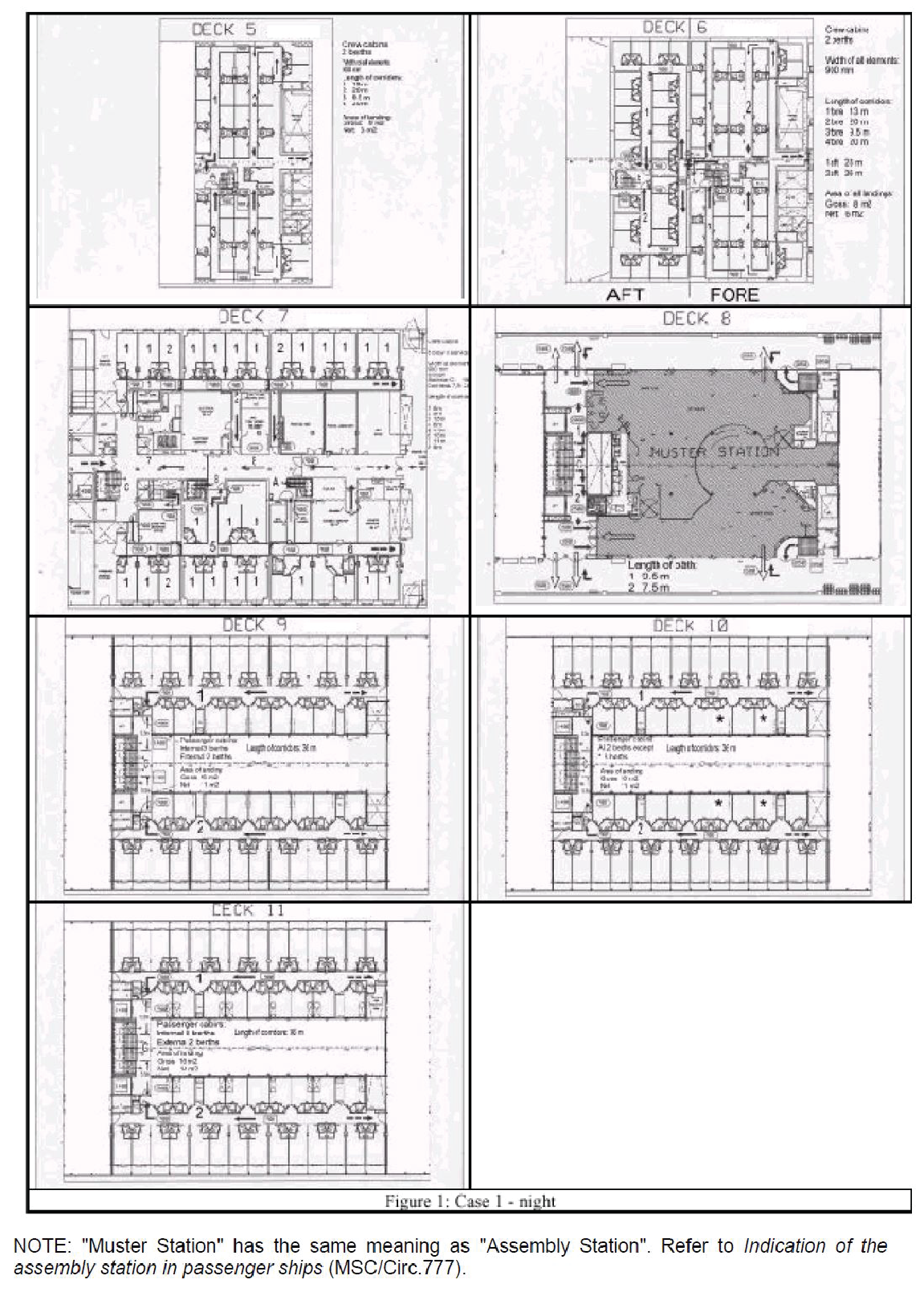
2.1 The example is limited to two main vertical zones (MVZ 1 and MVZ 2) of a
hypothetical cruise ship. For MVZ 1, a night scenario is considered, hereinafter
called case 1 (see figure 1) while a day scenario (case 2, see figure 2) is
considered for MVZ 2.
2.2 In case 1, the initial distribution corresponds to a total of 449 persons located
in the crew and passengers cabins as follows: 42 in deck 5; 65 in deck 6 (42 in the
fore part and 23 in the aft part); 26 in deck 7; 110 in deck 9; 96 in deck 10; and
110 in deck 11. Deck 8 (assembly station) is empty.
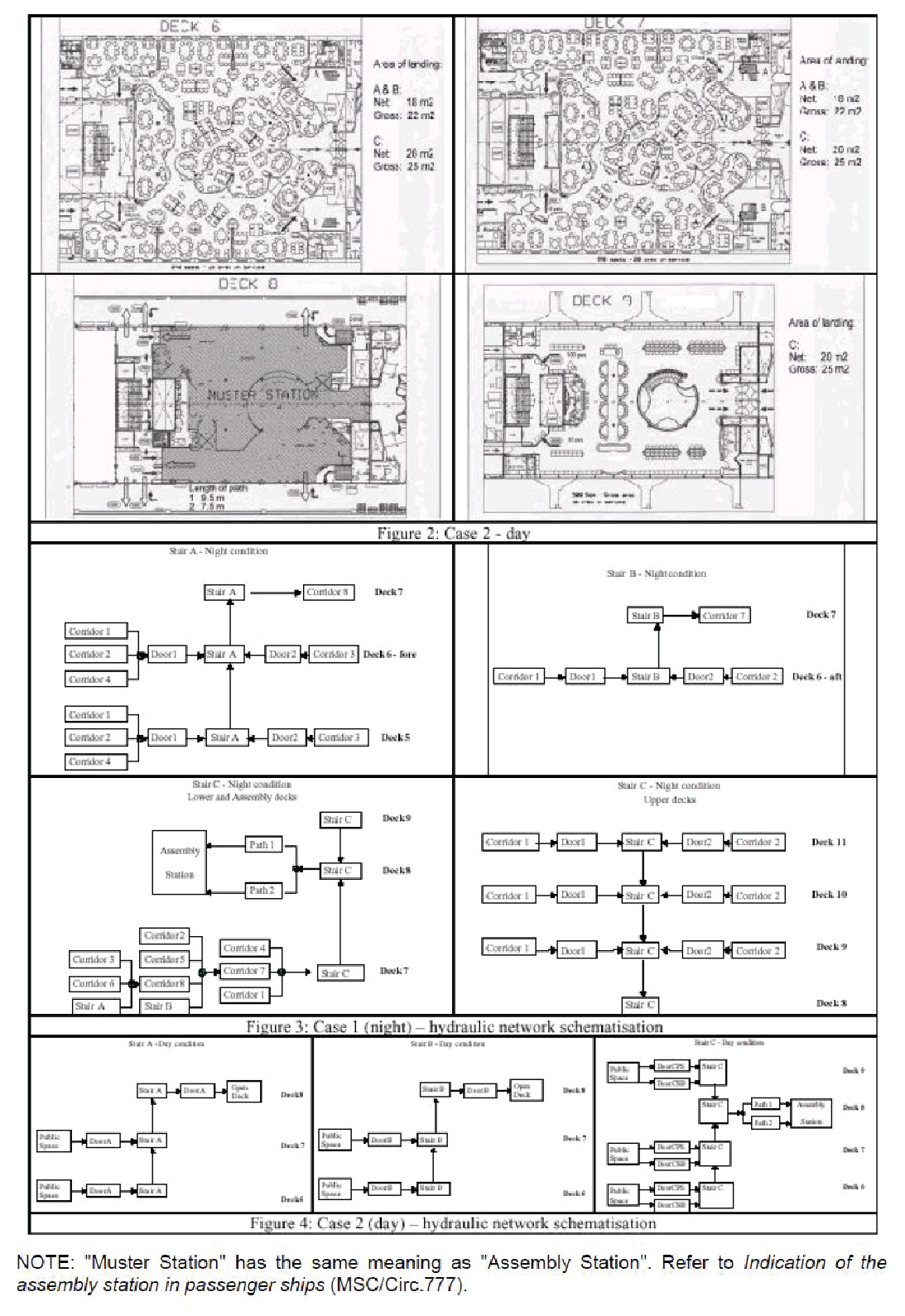
2.3 In case 2, the initial distribution corresponds to a total of 1,138 persons
located in the public spaces as follows: 469 in deck 6; 469 in deck 7; and 200 in
deck 9. Deck 8 (assembly station) is empty.
3 Description of the
system
3.1 Identification of assembly stations
For both MVZ 1 and MVZ 2, the assembly stations are located at deck 8,
which is also the embarkation deck.
3.2 Identification of escape routes
3.2.1 In MVZ 1, the escape routes are as follows (see figure 3):
-
.1 Deck 5 is connected with deck 6 (and then deck 8 where assembly stations
are located) through one stair (stair A) in the fore part of the zone. Four
corridors (corridors 1, 2, 3 and 4) and two doors (respectively door 1 and
2) connect the cabins with stair A. The clear widths and lengths are:
| Item
|
Wc (clear
width)[m]
|
Length
[m]
|
Area
[m2]
|
Notes
|
| MVZ1 – deck 5 – corridor
1
|
0.9
|
13
|
11.7
|
To door
1
|
| MVZ1 – deck 5 – corridor
2
|
0.9
|
20
|
18
|
To door
1
|
| MVZ1 – deck 5 – corridor
3
|
0.9
|
9.5
|
8.55
|
To door
2
|
| MVZ1 – deck 5 – corridor
4
|
0.9
|
20
|
18
|
To door
1
|
| MVZ1 – deck 5 – door 1
|
0.9
|
N.A.
|
N.A.
|
To stair
A
|
| MVZ1 – deck 5 – door 2
|
0.9
|
N.A.
|
N.A.
|
To stair
A
|
| MVZ1 – deck 5 – stair A
|
1.35
|
4.67
|
N.A.
|
Up to deck
6
|
-
.2 Deck 6 is connected with deck 7 (and then deck 8) through two stairs
(stairs A and B respectively in the fore and aft part of the zone). Four
corridors (corridors 1, 2, 3 and 4) and two doors (doors 1 and 2) connect
the fore cabins with stair A; and two corridors (corridors 5 and 6) and two
doors (doors 3 and 4) connect the aft cabins with stair B. The clear widths
and lengths are:
| Item
|
Wc (clear width)[m]
|
Length [m]
|
Area [m2]
|
Notes
|
| MVZ1 – deck 6 – corridor 1
|
0.9
|
13
|
11.7
|
To door 1
|
| MVZ1 – deck 6 – corridor 2
|
0.9
|
20
|
18
|
To door 1
|
| MVZ1 – deck 6 – corridor 3
|
0.9
|
9.5
|
8.55
|
To door 2
|
| MVZ1 – deck 6 – corridor 4
|
0.9
|
20
|
18
|
To door 1
|
| MVZ1 – deck 6 – door 1
|
0.9
|
N.A.
|
N.A.
|
To stair A
|
| MVZ1 – deck 6 – door 2
|
0.9
|
N.A.
|
N.A.
|
To stair A
|
| MVZ1 – deck 6 – stair A
|
1.35
|
4.67
|
N.A.
|
Up to deck 7
|
| MVZ1 – deck 6 – corridor 5
|
0.9
|
13
|
11.7
|
To door 3
|
| MVZ1 – deck 6 – corridor 6
|
0.9
|
20
|
18
|
To door 4
|
| MVZ1 – deck 6 – door 3
|
0.9
|
N.A.
|
N.A.
|
To stair B
|
| MVZ1 – deck 6 – door 4
|
0.9
|
N.A.
|
N.A.
|
To stair B
|
| MVZ1 – deck 6 – stair B
|
1.35
|
4.67
|
N.A.
|
Up to deck 7
|
- .3 Deck 7 is connected with deck 8 through stair C (stairs A and B
coming from below stop at deck 7). Arrival of stairs A and B and deck 7 cabins
are connected to stair C through 8 corridors, doors are neglected here in view
of simplifying this example. The clear widths and lengths are:
| Item
|
Wc (clear
width) [m]
|
Length
[m]
|
Area
[m2]
|
Notes
|
| MVZ1 – deck 7 – corridor
1
|
0.9
|
6
|
5.4
|
To stair
C
|
| MVZ1 – deck 7 – corridor
2
|
0.9
|
9
|
8.1
|
To corridor
7
|
| MVZ1 – deck 7 – corridor
3
|
0.9
|
1.5
|
13.5
|
To corridor
8
|
| MVZ1 – deck 7 – corridor
4
|
0.9
|
6
|
5.4
|
To stairway
C
|
| MVZ1 – deck 7 – corridor
5
|
0.9
|
14
|
12.6
|
To corridor
7
|
| MVZ1 – deck 7 – corridor
6
|
0.9
|
15
|
13.5
|
To corridor
8
|
| MVZ1 – deck 7 – corridor
7
|
2.4
|
11
|
26.4
|
From stair
B
|
| MVZ1 – deck 7 –
corridor 8
|
2.4
|
9
|
21.6
|
From stair A to stair C
|
| MVZ1 – deck 7 – stair C
|
1.40
|
4.67
|
N.A.
|
Up to deck
8
|
- .4 Deck 11 is connected with deck 10 through a double stair (stair
C) in the aft part of the zone. Two corridors (corridor 1 and 2) connect the
cabins with stair C through two doors (respectively doors 1 and 2). The clear
widths and lengths are:
| Item
|
Wc (clear width) [m]
|
Length [m]
|
Area [m2]
|
Notes
|
| MVZ1 – deck 11 – corridor
1
|
0.9
|
36
|
32.4
|
To door
1
|
| MVZ1 – deck 11 – corridor
2
|
0.9
|
36
|
32.4
|
To door
2
|
| MVZ1 – deck 11 – door
1
|
0.9
|
N.A.
|
N.A.
|
To stair
C
|
| MVZ1 – deck 11 – door 2
|
0.9
|
N.A.
|
N.A.
|
To stair
C
|
| MVZ1 – deck 11 – stair
C
|
2.8
|
4.67
|
N.A.
|
down to deck
10
|
- .5 Deck 10 has a similar arrangement as deck 11. The clear widths
and lengths are:
| Item
|
Wc (clear width) [m]
|
Length [m]
|
Area [m2]
|
Notes
|
| MVZ1 – deck 10 – corridor
1
|
0.9
|
36
|
32.4
|
To door
1
|
| MVZ1 – deck 10 – corridor
2
|
0.9
|
36
|
32.4
|
To door
2
|
| MVZ1 – deck 10 – door
1
|
0.9
|
N.A.
|
N.A.
|
To stair
C
|
| MVZ1 – deck 10 – door 2
|
0.9
|
N.A.
|
N.A.
|
To stair
C
|
| MVZ1 – deck 10 – stair
C
|
2.8
|
4.67
|
N.A.
|
down to deck
9
|
- .6 Deck 9 has a similar arrangement as deck 11. The clear widths and
lengths are:
| Item
|
Wc (clear width) [m]
|
Length [m]
|
Area [m2]
|
Notes
|
| MVZ1 – deck 9 – corridor
1
|
0.9
|
36
|
32.4
|
To door
1
|
| MVZ1 – deck 9 – corridor
2
|
0.9
|
36
|
32.4
|
To door
2
|
| MVZ1 – deck 9 – door 1
|
0.9
|
N.A.
|
N.A.
|
To stair
C
|
| MVZ1 – deck 9 – door 2
|
0.9
|
N.A.
|
N.A.
|
To stair
C
|
| MVZ1 – deck 9 – stair C
|
2.8
|
4.67
|
N.A.
|
down to deck
8
|
- .7 Deck 8, people coming from decks 5, 6 and 7 (stair C) and from
decks 11, 10 and 9 (stair C) enters the assembly station through paths 1 and 2.
The clear widths and lengths are:
| Item
|
Wc (clear
width) [m]
|
Length
[m]
|
Notes
|
| MVZ1 – deck 8 – path 1
|
2.00
|
9.50
|
to assembly station
|
| MVZ1 – deck 8 – path 2
|
2.50
|
7.50
|
to assembly station
|
3.2.2 In MVZ 2, the escape routes are as follows (see figure 4):
- .1 Deck 6 is connected with deck 7 (and then deck 8 where
assembly stations are located) through two stairs (stair A and B
respectively) in the fore part of the zone and through a double stair (stair
C) in the aft part of the zone. Two doors (respectively door A and B)
connect the public space with stairs A and B; and two doors (respectively
door port side (PS) and door starboard side (SB)) connect the public space
with stair C. The clear widths and lengths are:
| Item
|
Wc (clear
width) [m]
|
Length
[m]
|
Notes
|
| MVZ2 – deck 6 – door A
|
1
|
N.A.
|
|
| MVZ2 – deck 6 – door B
|
1
|
N.A.
|
|
| MVZ2 – deck 6 – door C
PS
|
1.35
|
N.A.
|
|
| MVZ2 – deck 6 – door C
SB
|
1.35
|
N.A.
|
|
| MVZ2 – deck 6 – stair
A
|
1.4
|
4.67
|
up to deck 7
|
| MVZ2 – deck 6 – stair
B
|
1.4
|
4.67
|
up to deck 7
|
| MVZ2 – deck 6 – stair
C
|
3.2
|
4.67
|
up to deck 7
|
- .2 deck 7 is connected with deck 8 through the same arrangements as
deck 6 to deck 7. The clear widths and lengths are:
| Item
|
Wc (clear
width) [m]
|
Length
[m]
|
Notes
|
| MVZ2 – deck 7 – door A
|
1.7
|
N.A.
|
|
| MVZ2 – deck 7 – door B
|
1.7
|
N.A.
|
|
| MVZ2 – deck 7 – door C
PS
|
0.9
|
N.A.
|
|
| MVZ2 – deck 7 – door C
SB
|
0.9
|
N.A.
|
|
| MVZ2 – deck 7 – stair
A
|
2.05
|
4.67
|
up to deck 8
|
| MVZ2 – deck 7 – stair
B
|
2.05
|
4.67
|
up to deck 8
|
| MVZ2 – deck 7 – stair C
|
3.2
|
4.67
|
up to deck 8
|
- .3 Deck 9 is connected with deck 8 through a double stair (stair C)
in the aft part of the zone. Two doors (respectively door PS and door SB)
connect the public space with stair C. The clear widths and lengths are:
| Item
|
Wc (clear
width) [m]
|
Length
[m]
|
Notes
|
| MVZ2 – deck 9 – door C
PS
|
1
|
N.A.
|
|
| MVZ2 – deck 9 – door C
SB
|
1
|
N.A.
|
|
| MVZ2 – deck 9 – stair
C
|
3.2
|
4.67
|
down to deck 7
|
- .4 Deck 8, people coming from decks 6 and 7 (stairs A and B) enter
directly the embarkation station (open deck) through doors A and B, while people
coming from deck 9 (stair C) enter the assembly (muster) station through paths 1
and 2. The clear widths and lengths are:
| Item
|
Wc (clear
width) [m]
|
Length
[m]
|
Notes
|
| MVZ2 – deck 8 – door
A
|
2.05
|
N.A.
|
to embarkation station
|
| MVZ2 – deck 8 – door
B
|
2.05
|
N.A.
|
to embarkation station
|
| MVZ2 – deck 8 – path
1
|
2
|
9.5
|
to assembly station
|
| MVZ2 – deck 8 – path
2
|
2.5
|
7.5
|
to assembly station
|
4 Scenarios considered
4.1 Case 1 refers to a day scenario in MVZ 1, according to chapter 13 of the FSS
Code, the 449 persons are initially distributed as follows: 42 in deck 5; 65 in deck
6 (42 in the fore part and 23 in the aft part); 26 in deck 7; 110 in deck 9; 96 in
deck 10; and 110 in deck 11. Deck 8 (assembly station) is empty. In accordance with
paragraph 2.2 of appendix 1 to the guidelines, all persons in the cabins are assumed
to simultaneously move into the corridors. The corresponding initial conditions
are:
| MVZ 1 –
Corridors
|
Persons
|
Initial
density D (p/m2)
|
Initial
specific flow Fs (p/m/s)
|
Calculated
flow Fc (p/s)
|
Initial speed
of persons S (m/s)
|
| Deck 5 – corridor 1
|
11
|
0.94
|
0.85
|
0.77
|
1.03
|
| Deck 5 – corridor 2
|
12
|
0.67
|
0.73
|
0.65
|
1.14
|
| Deck 5 – corridor 3
|
8
|
0.94
|
0.85
|
0.77
|
1.04
|
| Deck 5 – corridor 4
|
11
|
0.61
|
0.7
|
0.63
|
1.16
|
| Deck 6 – corridor 1
|
11
|
0.94
|
0.85
|
0.77
|
1.03
|
| Deck 6 – corridor 2
|
12
|
0.67
|
0.73
|
0.65
|
1.14
|
| Deck 6 – corridor 3
|
8
|
0.94
|
0.85
|
0.77
|
1.04
|
| Deck 6 – corridor 4
|
11
|
0.61
|
0.7
|
0.63
|
1.16
|
| Deck 6 – corridor 5
|
11
|
0.94
|
0.85
|
0.77
|
1.03
|
| Deck 6 – corridor 6
|
12
|
0.67
|
0.73
|
0.65
|
1.14
|
| Deck 7 – corridor 1
|
4
|
0.74
|
0.76
|
0.69
|
1.11
|
| Deck 7 – corridor 2
|
4
|
0.49
|
0.64
|
0.58
|
1.2
|
| Deck 7 – corridor 3
|
6
|
0.44
|
0.58
|
0.52
|
1.2
|
| Deck 7 – corridor 4
|
4
|
0.74
|
0.76
|
0.69
|
1.11
|
| Deck 7 – corridor 5
|
6
|
0.48
|
0.62
|
0.56
|
1.2
|
| Deck 7 – corridor 6
|
2
|
0.15
|
0.19
|
0.17
|
1.2
|
| Deck 7 – corridor 7
|
0
|
0
|
N.A.
|
N.A.
|
N.A.
|
| Deck 7 – corridor 8
|
0
|
0
|
N.A.
|
N.A.
|
N.A.
|
| Deck 11 – corridor 1
|
55
|
1.7
|
1.21
|
1.09
|
0.75
|
| Deck 11 – corridor
|
55
|
1.7
|
1.21
|
1.09
|
0.75
|
| Deck 10 – corridor 1
|
48
|
1.48
|
1.11
|
1
|
0.83
|
| Deck 10 – corridor 2
|
48
|
1.48
|
1.11
|
1
|
0.83
|
| Deck 9 – corridor 1
|
55
|
1.7
|
1.21
|
1.09
|
0.74
|
| Deck 9 – corridor 2
|
55
|
1.7
|
1.21
|
1.09
|
0.74
|
| MVZ 1 – Stairs, doors & corridors
|
Persons (N)
|
Specific flow Fs in (p/m/s)
|
Max. specific flow Fs (p/m/s)
|
Specific flow Fs (p/m/s)
|
Cal-culated flow Fc (p/s)
|
Speed of persons S (m/s)
|
Queue
|
Comments
|
Notes
|
| From current
route
|
Total including
those from other routes
|
| Deck 5 – door 1
|
34
|
34
|
2.28
|
1.3
|
1.3
|
1.17
|
N.A.
|
Yes
|
From corridors 1, 2 and 4
|
1
|
| Deck 5 – door 2
|
8
|
8
|
1.85
|
1.3
|
0.85
|
0.77
|
N.A.
|
|
From corridor 3
|
1
|
| Deck 5 – stair A
|
42
|
42
|
1.43
|
0.88
|
0.88
|
1.188
|
0.44
|
Yes
|
From doors 1 and 2
|
1, 2
|
| Deck 6 – door 1
|
34
|
34
|
2.58
|
1.30
|
1.3
|
1.17
|
N.A.
|
Yes
|
From corridors 1, 2, and 4;
|
1
|
| Deck 6 – door 2
|
8
|
8
|
0.85
|
1.30
|
0.85
|
0.77
|
N.A.
|
|
From corridor 3
|
1
|
| Deck 6 – stair A
|
42
|
84
|
2.32
|
0.88
|
0.88
|
1.188
|
0.44
|
Yes
|
From doors 1 and 2, from deck 5
|
1, 2
|
| Deck 6 – door 3
|
11
|
11
|
0.85
|
1.30
|
0.85
|
0.77
|
N.A.
|
|
From corridor 5
|
1
|
| Deck 6 – door 4
|
12
|
12
|
0.73
|
1.30
|
0.81
|
0.73
|
N.A.
|
|
From corridor 4
|
1
|
| Deck 6 – stair B
|
23
|
23
|
1.05
|
0.88
|
0.88
|
1.188
|
0.44
|
Yes
|
From doors 3 and 4
|
1, 2
|
| Deck 7 – corridor 8
|
8
|
92
|
0.78
|
1.3
|
0.78
|
1.88
|
1.09
|
|
From corridors 3 and 6, from deck 6, stair
A
|
1, 3
|
| Deck 7 – corridor 7
|
18
|
125
|
1.75
|
1.3
|
1.3
|
3.12
|
0.67
|
Yes
|
From corridors 2, 5 and 8, from deck 6, stair
B
|
1, 4
|
| Deck 7 – stair C
|
8
|
133
|
3.21
|
0.88
|
0.88
|
1.232
|
0.44
|
Yes
|
From corridors 1, 4 and 7; up to deck 8
|
1, 2, 5
|
| Deck 11 – door 1
|
55
|
55
|
1.21
|
1.3
|
1.21
|
1.09
|
N.A.
|
|
To stair C
|
1
|
| Deck 11 – door 2
|
55
|
55
|
1.21
|
1.3
|
1.21
|
1.09
|
N.A.
|
|
To stair C
|
1
|
| Deck 11 – stair C
|
110
|
110
|
0.78
|
1.1
|
0.78
|
2.17
|
0.81
|
|
Down to deck 10
|
1, 2
|
| Deck 10 – door 1
|
48
|
48
|
1.11
|
1.3
|
1.11
|
1
|
N.A.
|
|
To stair C
|
1
|
| Deck 10 – door 2
|
48
|
48
|
1.11
|
1.3
|
1.11
|
1
|
N.A.
|
|
To stair C
|
1
|
| Deck 10 – stair C
|
96
|
206
|
1.49
|
1.1
|
1.10
|
3.08
|
0.55
|
Yes
|
Down to deck 9
|
1, 2
|
| Deck 9 – door 1
|
55
|
55
|
1.21
|
1.3
|
1.21
|
1.09
|
N.A.
|
|
To stair C
|
1
|
| Deck 9 – door 2
|
55
|
55
|
1.21
|
1.3
|
1.21
|
1.09
|
N.A.
|
|
To stair C
|
1
|
| Deck 9 – stair C
|
110
|
316
|
1.88
|
1.1
|
1.10
|
3.08
|
0.55
|
Yes
|
Down to deck 8
|
1, 2
|
| Deck 8 – path 1
|
0
|
200
|
0.96
|
1.3
|
0.96
|
1.92
|
0.95
|
|
To assembly stat
|
1, 6
|
| Deck 8 – path 2
|
0
|
249
|
0.96
|
1.3
|
0.96
|
2.4
|
0.95
|
|
To assembly stat
|
1, 6
|
Notes:
1 The specific flow "Fs in" is the specific flow entering the element of the escape
route; the maximum specific flow is the maximum allowable flow given in table 1.3 of
appendix 1 of the guidelines; the specific flow is the one applicable for the
calculations i.e. the minimum between "Fs in" and the maximum allowable; when "Fs
in" is greater than the maximum allowable, a queue is formed.
2 Some stairs are used by both persons coming from below (or above) and persons
coming from the current deck considered; in making the calculation for a stair
connecting deck N to deck N+1 (or deck N-1), the persons to be considered are those
entering the stairs at deck N plus those coming from all decks below (or above) deck
N.
3 At deck 7, 8 persons initially move from the cabins into corridor 8 and 84 persons
arrive to corridor 8 from deck 6, stair A; the total is therefore 92 persons.
4 At deck 7, 18 persons initially move from the cabins into corridor 7, 23 persons
arrive to corridor 7 from deck 6 stair B and 84 persons arrive to corridor 8 from
deck 7, corridor 7; the total is, therefore, 125 persons.
5 At deck 7, 8 persons initially move from the cabins directly to the stair C and 125
persons arrive to stair C from corridor 8; the total is therefore 133 persons.
6 At deck 8 (assembly station), no persons are initially present; therefore, the
escape routes on this deck are then used by the total number of persons arriving
from above and/or below.
4.2 Case 2 refers to a day scenario in MVZ 2, according to chapter 13 of the FSS
Code, the 1,138 persons are initially distributed as follows: 469 in deck 6; 469 in
deck 7; and 200 in deck 9. Deck 8 (assembly station) is initially empty. In
accordance with paragraph 2.2 of appendix 1 to the guidelines, all persons are
assumed to simultaneously begin the evacuation and use the exit doors at their
maximum specific flow. The corresponding initial conditions are:
| MVZ 2 – Doors
|
Persons
|
Initial density D
(p/m2)
|
Initial Specific flow Fs (p/m/s)
|
Calculated flow Fc (p/s)
|
Initial speed of persons S (m/s)
|
| Deck 6 – door A
|
100
|
N.A.
|
1.3
|
1.3
|
N.A.
|
| Deck 6 – door B
|
100
|
N.A.
|
1.3
|
1.3
|
N.A.
|
| Deck 6 – door C PS
|
134
|
N.A.
|
1.3
|
1.76
|
N.A.
|
| Deck 6 – door C SB
|
135
|
N.A.
|
1.3
|
1.76
|
N.A.
|
| Deck 7 – door A
|
170
|
N.A.
|
1.3
|
2.21
|
N.A.
|
| Deck 7 – door B
|
170
|
N.A.
|
1.3
|
2.21
|
N.A.
|
| Deck 7 – door C PS
|
65
|
N.A.
|
1.3
|
1.17
|
N.A.
|
| Deck 7 – door C SB
|
64
|
N.A.
|
1.3
|
1.17
|
N.A.
|
| Deck 9 – door C SB
|
100
|
N.A.
|
1.3
|
1.3
|
N.A.
|
| Deck 9 – door C PS
|
100
|
N.A.
|
1.3
|
1.3
|
N.A.
|
| MVZ 2 – Stairs
|
Persons (N)
|
Specific flow Fs in (p/m/s)
|
Max. specific flow Fs (p/m/s)
|
Specific flow Fs (p/m/s)
|
Calculated flow Fc (p/s)
|
Speed of persons S (m/s)
|
Queue
|
Comments
|
Notes
|
| From current
route
|
Total including
those from other routes
|
| Deck 6 – stair A
|
100
|
100
|
0.93
|
0.88
|
0.88
|
1.23
|
0.44
|
Yes
|
up to deck 7
|
1
|
| Deck 6 – stair B
|
100
|
100
|
0.93
|
0.88
|
0.88
|
1.23
|
0.44
|
Yes
|
up to deck 7
|
1
|
| Deck 6 – stair C
|
269
|
269
|
1.1
|
0.88
|
0.88
|
2.82
|
0.44
|
Yes
|
up to deck
7
|
1
|
| Deck 7 – stair A
|
170
|
270
|
1.68
|
0.88
|
0.88
|
1.8
|
0.44
|
Yes
|
up to deck
8
|
1, 2
|
| Deck 7 – stair B
|
170
|
270
|
1.68
|
0.88
|
0.88
|
1.8
|
0.44
|
Yes
|
up to deck
8
|
1, 2
|
| Deck 7 – stair C
|
129
|
398
|
1.61
|
0.88
|
0.88
|
2.82
|
0.44
|
Yes
|
up to deck
8
|
1, 2
|
| Deck 9 – stair C
|
200
|
200
|
0.81
|
1.1
|
1.81
|
2.60
|
0.78
|
|
down to deck
8
|
|
| Deck 8 – path 1
|
0
|
266
|
1.2
|
1.3
|
1.2
|
2.41
|
0.75
|
|
from decks 7 and
9
|
1, 3
|
| Deck 8 – path 2
|
0
|
332
|
1.2
|
1.3
|
1.2
|
3.01
|
0.75
|
|
from decks 7 and
9
|
1, 3
|
| Deck 8 – door A
|
0
|
270
|
0.88
|
1.3
|
0.88
|
1.8
|
N.A.
|
|
from deck 7
|
1, 3
|
| Deck 8 – door B
|
0
|
270
|
0.88
|
1.3
|
0.88
|
1.8
|
N.A.
|
|
from deck 7
|
1, 3
|
Notes:
- 1 The specific flow "Fs in" is the specific flow entering the element of the
escape route; the maximum specific flow is the maximum allowable flow given in
table 1.3 of appendix 1 of the guidelines; the specific flow is the one
applicable for the calculations i.e. the minimum between "Fs in" and the maximum
allowable; when "Fs in" is greater than the maximum allowable, a queue is
formed.
- 2 Some stairs are used by both persons coming from below (or above) and persons
coming from the current deck considered; in making the calculation for a stair
connecting deck N to deck N+1 (or deck N-1), the persons to be considered are
those entering the stairs at deck N plus those coming from all decks below (or
above) deck N.
- 3 At deck 8 (assembly station), no persons are initially present; therefore, the
escape routes on this deck are then used by the total number of persons arriving
from above and/or below.
5 Calculation of tF, tdeck and
tstair
5.1 For case 1:
| Item
|
Persons N
|
Length L (m)
|
Calculated flow Fc
(p/s)
|
Speed S (m/s)
|
Flow dur. tF (s)
tF = N/ Fc
|
Deck or stairs dur.,
tdeck, tstairs T = L/S
|
Entering
|
| Deck 5 – corridor 1
|
11
|
13
|
0.77
|
1.03
|
14.3
|
12.6
|
Door 1
|
| Deck 5 – corridor 2
|
12
|
20
|
0.65
|
1.14
|
18.3
|
17.6
|
Door 1
|
| Deck 5 – corridor 3
|
8
|
9.5
|
0.77
|
1.04
|
10.4
|
9.2
|
Door 2
|
| Deck 5 – corridor 4
|
11
|
20
|
0.63
|
1.16
|
17.4
|
17.3
|
Door 1
|
| Deck 5 – door 1
|
34
|
N.A.
|
1.17
|
N.A.
|
29.1
|
N.A.
|
Stairs A
|
| Deck 5 – door 2
|
8
|
N.A.
|
0.77
|
N.A.
|
10.4
|
N.A.
|
Stair A
|
| Deck 5 – stair A
|
42
|
4.67
|
1.188
|
0.44
|
35.4
|
10.6
|
Deck 6
|
| Deck 6 – corridor 1
|
11
|
13
|
0.77
|
1.03
|
14.3
|
12.6
|
Door 1
|
| Deck 6 – corridor 2
|
12
|
20
|
0.65
|
1.14
|
18.3
|
17.6
|
Door 1
|
| Deck 6 – corridor 3
|
8
|
9.5
|
0.77
|
1.04
|
10.4
|
9.2
|
Door 2
|
| Deck 6 – corridor 4
|
11
|
20
|
0.63
|
1.16
|
17.4
|
17.3
|
Door 1
|
| Deck 6 – door 1
|
34
|
N.A.
|
1.17
|
N.A.
|
29.1
|
N.A.
|
Stair A
|
| Deck 6 – door 2
|
8
|
N.A.
|
0.77
|
N.A.
|
10.4
|
N.A.
|
Stair A
|
| Deck 6 – stair A
|
84
|
4.67
|
1.188
|
0.44
|
70.7
|
10.6
|
Deck 7
|
| Deck 6 – corridor 5
|
11
|
13
|
0.77
|
1.03
|
14.3
|
12.6
|
Door 3
|
| Deck 6 – corridor 6
|
12
|
20
|
0.65
|
1.14
|
18.3
|
17.6
|
Door 4
|
| Deck 6 – door 3
|
11
|
N.A.
|
0.77
|
N.A.
|
14.3
|
N.A.
|
Stair B
|
| Deck 6 – door 4
|
12
|
N.A.
|
0.65
|
N.A.
|
18.3
|
N.A.
|
Stair B
|
| Deck 6 – stair B
|
23
|
4.67
|
1.188
|
0.44
|
19.4
|
10.6
|
Deck 7
|
| Deck 7 – corridor 1
|
4
|
6
|
0.69
|
1.11
|
5.8
|
5.4
|
Stair C
|
| Deck 7 – corridor 2
|
4
|
9
|
0.58
|
1.2
|
6.9
|
7.5
|
Corridor 7
|
| Deck 7 – corridor 3
|
6
|
15
|
0.52
|
1.2
|
11.5
|
12.5
|
Corridor 8
|
| Deck 7 – corridor 4
|
4
|
6
|
0.69
|
1.11
|
5.8
|
5.4
|
Stair C
|
| Deck 7 – corridor 5
|
6
|
14
|
0.56
|
1.2
|
10.8
|
11.7
|
Corridor 7
|
| Deck 7 – corridor 6
|
2
|
15
|
0.17
|
1.2
|
11.5
|
12.5
|
Corridor 8
|
| Deck 7 – corridor 8
|
92
|
9
|
1.88
|
1.09
|
48.9
|
8.2
|
Corridor 7
|
| Deck 7 – corridor 7
|
125
|
11
|
3.12
|
0.67
|
40.1
|
16.4
|
Stair C
|
| Deck 7 – stair C
|
133
|
4.67
|
1.232
|
0.44
|
108
|
10.6
|
Deck 8
|
| Deck 11– corridor 1
|
55
|
36
|
1.09
|
0.75
|
50.7
|
48.2
|
Door 1
|
| Deck 11– corridor 2
|
55
|
36
|
1.09
|
0.75
|
50.7
|
48.2
|
Door 2
|
| Deck 11 – door 1
|
55
|
N.A.
|
1.09
|
N.A.
|
50.7
|
N.A.
|
Stair C
|
| Deck 11 – door 2
|
55
|
N.A.
|
1.09
|
N.A.
|
50.7
|
N.A.
|
Stair C
|
| Deck 11 – stair C
|
110
|
4.67
|
2.17
|
0.81
|
50.7
|
5.8
|
Deck 10
|
| Deck 10– corridor 1
|
48
|
36
|
1
|
0.83
|
48.2
|
43.5
|
Door 1
|
| Deck 10– corridor 2
|
48
|
36
|
1
|
0.83
|
48.2
|
43.5
|
Door 2
|
| Deck 10 – door 1
|
48
|
N.A.
|
1
|
N.A.
|
48.2
|
N.A.
|
Stair C
|
| Deck 10 – door 2
|
48
|
N.A.
|
1
|
N.A.
|
48.2
|
N.A.
|
Stair C
|
| Deck 10 – stair C
|
206
|
4.67
|
3.08
|
0.55
|
66.9
|
8.5
|
Deck 9
|
| Deck 9 – corridor 1
|
55
|
36
|
1.09
|
0.74
|
50.7
|
48.4
|
Door 1
|
| Deck 9 – corridor 2
|
55
|
36
|
1.09
|
0.74
|
50.7
|
48.4
|
Door 2
|
| Deck 9 – door 1
|
55
|
N.A.
|
1.09
|
N.A.
|
50.7
|
N.A.
|
Stair C
|
| Deck 9 – door 2
|
55
|
N.A.
|
1.09
|
N.A.
|
50.7
|
N.A.
|
Stair C
|
| Deck 9 – stair C
|
316
|
4.67
|
3.08
|
0.55
|
102.6
|
8.5
|
Deck 8
|
5.2 For case 2: since in this particular arrangement there are no corridors, the deck
duration is zero.
| Item
|
Persons N
|
Length L (m)
|
Calculated flow Fc
(p/s)
|
Speed S (m/s)
|
Flow dur. tF (s)
tF = N/ Fc
|
Deck or stairs dur.,
tdeck, tstairs t = L/S
|
Entering
|
| Deck 6 – door A
|
100
|
N.A.
|
1.3
|
N.A.
|
76.9
|
N.A.
|
Stair A
|
| Deck 6 – door B
|
100
|
N.A.
|
1.3
|
N.A.
|
76.9
|
N.A.
|
Stair B
|
| Deck 6 – door C PS
|
134
|
N.A.
|
1.76
|
N.A.
|
76.4
|
N.A.
|
Stair C
|
| Deck 6 – door C SB
|
135
|
N.A.
|
1.76
|
N.A.
|
76.9
|
N.A.
|
Stair C
|
| Deck 6 – stair A
|
100
|
4.67
|
1.23
|
0.44
|
81.2
|
10.6
|
Deck 7
|
| Deck 6 – stair B
|
100
|
4.67
|
1.23
|
0.44
|
81.2
|
10.6
|
Deck 7
|
| Deck 6 – stair C
|
269
|
4.67
|
2.82
|
0.44
|
95.5
|
10.6
|
Deck 7
|
| Deck 7 – door A
|
170
|
N.A.
|
2.21
|
N.A.
|
76.9
|
N.A.
|
Stair A
|
| Deck 7 – door B
|
170
|
N.A.
|
2.21
|
N.A.
|
76.9
|
N.A.
|
Stair B
|
| Deck 7 – door C PS
|
65
|
N.A.
|
1.17
|
N.A.
|
55.6
|
N.A.
|
Stair C
|
| Deck 7 – door C SB
|
64
|
N.A.
|
1.17
|
N.A.
|
54.7
|
N.A.
|
Stair C
|
| Deck 7 – stair A
|
270
|
4.67
|
1.8
|
0.44
|
149.7
|
10.6
|
Deck 8
|
| Deck 7 – stair B
|
270
|
4.67
|
1.8
|
0.44
|
149.7
|
10.6
|
Deck 8
|
| Deck 7 – stair C
|
398
|
4.67
|
2.82
|
0.44
|
141.3
|
10.6
|
Deck 8
|
| Deck 8 – door A
|
270
|
N.A.
|
1.8
|
N.A.
|
149.7
|
N.A.
|
Embarkation
|
| Deck 8 – door B
|
270
|
N.A.
|
1.8
|
N.A.
|
149.7
|
N.A.
|
Embarkation
|
| Deck 9 – door PS
|
100
|
N.A.
|
1.3
|
N.A.
|
76.9
|
N.A.
|
Stair C
|
| Deck 9 – door SB
|
100
|
N.A.
|
1.3
|
N.A.
|
76.9
|
N.A.
|
Stair C
|
| Deck 9 – stair C
|
200
|
4.67
|
2.6
|
0.78
|
76.9
|
6
|
Deck 8
|
6 Calculation of tassembly
6.1 Case 1: In this case, all the 429 persons use stair C (316 coming from above deck
8 and 133 from below) and, once arrived at deck 8, need to travel on deck 8 to reach
the assembly station using either path 1 or path 2. The corresponding duration is as
follows:
| Item
|
Persons N
|
Length L (m)
|
Calculated flow Fc
(p/s)
|
Speed S (m/s)
|
Flow dur. tF (s)
tF = N/ Fc
|
tassembly t =
L/S
|
Entering
|
| Deck 8 – path 1
|
200
|
9.5
|
1.92
|
0.95
|
104.4
|
10
|
Assembly
station
|
| Deck 8 – path 2
|
249
|
7.5
|
2.4
|
0.95
|
103.9
|
7.9
|
Assembly
station
|
6.2 Case 2: In this case, all the persons using stair C (totalling 598), once arrived
at deck 8, need to travel through on deck 8 to reach the assembly station using
either path 1 or path 2. The corresponding duration is as follows:
| Item
|
Persons
N
|
Length L
(m)
|
Calculated flow Fc (p/s)
|
Speed S
(m/s)
|
Flow dur.
tF (s) tF = N/ Fc
|
tassembly t = L/S
|
Entering
|
| Deck 8 – path 1
|
266
|
9.5
|
2.41
|
0.75
|
110.5
|
12.7
|
Assembly station
|
| Deck 8 – path 2
|
332
|
7.5
|
3.01
|
0.75
|
110.3
|
10
|
Assembly station
|
7 Calculation of T
7.1 Case 1: The travel duration T, according to appendix 1 to the interim guidelines,
is the maximum tI (equation 2.2.11) multiplied by 2.3 (sum of correction
factor and counterflow correction factor). The maximum values of tI for
each escape route are given in the following:
| Escape route on
|
Tdeck
|
tf
|
tstairs
|
tassembly
|
tl
|
T
|
Notes
|
| Deck 11
|
48.2
|
104.4
|
22.7
|
10
|
185.3
|
426.2
|
1
|
| Deck 10
|
43.5
|
104.4
|
17
|
10
|
174.8
|
402
|
1, 2
|
| Deck 9
|
48.4
|
104.4
|
8.5
|
10
|
171.3
|
394
|
1, 2
|
| Deck 8
|
0
|
104.4
|
0
|
10
|
114.4
|
286.1
|
|
| Deck 7
|
37.1
|
108
|
10.6
|
10
|
163.9
|
377
|
1
|
| Deck 6 – stair A (fore)
|
42.4
|
108
|
21.2
|
10
|
179.6
|
413.1
|
1, 3
|
| Deck 6 – stair B (aft)
|
34
|
108
|
21.2
|
10
|
170.2
|
391.5
|
1, 3
|
| Deck 5
|
42.2
|
108
|
31.8
|
10
|
190.2
|
437.5
|
1, 3
|
- Notes:
- 1 The flow duration, tf, is the maximum flow duration recorded on the
whole escape route from the deck where persons started evacuating up to the
assembly station.
- 2 The travel duration on the stairways (tstair) is the total duration
necessary to travel along all the stairs from the deck where persons originally
started evacuating up to the deck where the assembly station is located; in the
present case, tstair for persons moving down from deck 11 is,
therefore, the sum of tstair from deck 11 to 10 (5.7 s), from deck 10
to 9 (8.5 s) and from deck 9 to 8 (8.5 s), in total 22.7 s; similarly for the
other cases.
- 3 The travel duration on the stairways (tstair) is the total duration
necessary to travel along all the stairs from the deck where persons originally
started evacuating up to the deck where the assembly station is located; in the
present case, tstair for persons moving up from deck 5 is, therefore,
the sum of tstair from deck 5 to 6 (10.6 s.), from deck 6 to 7 (10.6
s) and from deck 7 to 8 (10.6 s), in total 31.8 s; similarly for the other
cases.
Accordingly, the corresponding value of T is 437.5 s.
7.2 Case 2: The travel duration T, according to appendix 1 to the guidelines, is the
maximum tI equation 2.2.11) multiplied by 2.3 (sum of correction factor
and counterflow correction factor). The maximum values of tI for each
escape route are given in the following:
| Escape
route on
|
Tdeck
|
tf
|
tstairs
|
tassembly
|
tl
|
T
|
Notes
|
| Deck 9
|
0
|
110.4
|
6
|
12.7
|
168.3
|
387.2
|
1, 2
|
| Deck 8
|
0
|
104.4
|
0
|
12.7
|
162.4
|
373.4
|
|
| Deck 7 – stair A
|
0
|
149.7
|
10.6
|
0
|
160.3
|
368.6
|
|
| Deck 7 – stair B
|
0
|
149.7
|
10.6
|
0
|
160.3
|
368.6
|
|
| Deck 7 – stair C
|
0
|
141.3
|
10.6
|
12.7
|
164.6
|
378.7
|
2
|
| Deck 6 – stair A
|
0
|
149.7
|
21.2
|
0
|
170.9
|
393
|
1, 3
|
| Deck 6 – stair B
|
0
|
149.7
|
21.2
|
0
|
170.9
|
393
|
1, 3
|
| Deck 6 – stair C
|
0
|
141.3
|
21.2
|
12.7
|
175.2
|
403.1
|
1, 2, 3
|
- Notes:
- 1 The flow duration, tf, is the maximum flow duration
recorded on the whole escape route from the deck where persons started
evacuating up to the assembly station.
- 2 In this example, stairs A and B are already leading to the
embarkation station; therefore, only those escape routes passing through stair C
need additional duration, tassembly, to reach the assembly station.
- 3 The travel duration on the stairways (tstair) is the
total duration necessary to travel along all the stairs from the deck where
persons originally started evacuating up to the deck where the assembly station
is located; in the present case, tstair for persons moving from deck
6 is therefore the sum of tstair from deck 6 to 7 (10.6 s) and from
deck 7 to 8 (10.6 s).
Accordingly, the corresponding value of T is 403.1 s.
8 Identification of congestion
8.1 Case 1: Congestion takes place on deck 5 (door 1 and stair A), deck 6 (door 1,
stairs A and B), deck 7 (corridor 7 and stair C), deck 10 (stair C) and deck 9
(stair C). However, since the total duration is below the limit (see paragraph 9.1
of this example) no design modifications are needed.
8.2 Case 2: Congestion takes place on deck 6 (stairs A, B and C) and deck 7 (stairs
A, B and C). However, since the total duration is below the limit (see paragraph 9.2
of this example) no design modifications are needed.
9 Performance standard
9.1 Case 1: The total evacuation duration, according to paragraph 5.1 of the revised
guidelines is as follows:
9.2 Case 2: The total evacuation duration, according to paragraph 5.1 of the revised
guidelines is as follows:
|