1 Closing devices for air intakes (paragraph 3.2.6)
1.1 The closing devices that need not be operable from within the single
spaces may be located in centralized positions.
1.2 Engine-room casings, cargo machinery spaces, electric motor rooms and
steering gear compartments are generally considered as spaces not covered by
paragraph 3.2.6 and, therefore, the requirement for closing devices need not be
applied to these spaces.
1.3 The closing devices should give a reasonable degree of gas tightness.
Ordinary steel fire-flaps without gaskets/seals should not be considered
satisfactory.
1.4 Regardless of this interpretation, the closing devices shall be
operable from outside of the protected space (SOLAS
regulation II-2/5.2.1.1).
2 Application of fire safety requirements in SOLAS chapter II-2 to
cargo machinery spaces and turret compartments (paragraphs 3.3.1 and 11.1.1.1)
The sentence "for the purpose of prevention of potential explosion
according to SOLAS regulation ll-2/4.5.10" in paragraph 3.3.1 does not
require application of the aforementioned SOLAS
regulation. SOLAS
regulation II-2/4.5.10 does not apply in accordance with
paragraph 11.1.1.1.
3 Cargo tank clearances (paragraphs 3.5.3.1.2 and 3.5.3.1.3)
Access through horizontal openings, hatches or manholes
3.1 The minimum clear opening of 600 mm x 600 mm may have corner radii up
to 100 mm maximum. In such a case where as a consequence of structural analysis of a
given design the stress is to be reduced around the opening, it is considered
appropriate to take measures to reduce the stress such as making the opening larger
with increased radii, e.g. 600 mm x 800 mm with 300 mm radii, in which a clear
opening of 600 mm x 600 mm with corner radii up to 100 mm maximum fits.
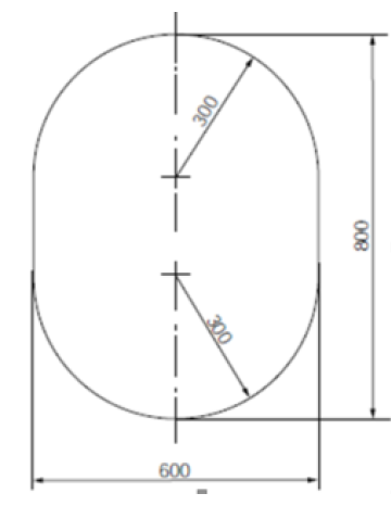
Access through vertical openings or manholes providing passage through
the length and breadth of the space
3.2 The minimum clear opening of not less than 600 mm x 800 mm may also
include an opening with corner radii of 300 mm. An opening of 600 mm in height x 800
mm in width may be accepted as access openings in vertical structures where it is
not desirable to make large openings in the structural strength aspects, i.e.
girders and floors in double bottom tanks.
3.3 Subject to verification of easy evacuation of an injured person on a stretcher
the vertical opening 850 mm x 620 mm with upper half wider than 600 mm, while the
lower half may be less than 600 mm with the overall height not less than 850 mm is
considered an acceptable alternative to the traditional opening of 600 mm x 800 mm
with corner radii of 300 mm.
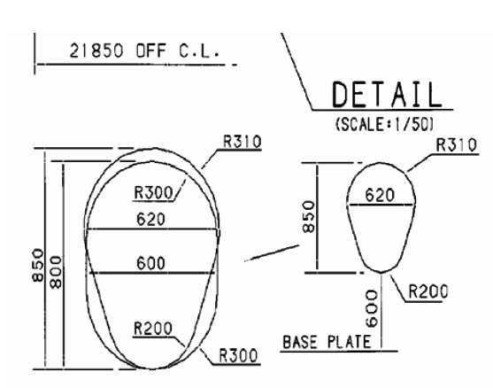
3.4 If a vertical opening is at a height of more than 600 mm steps and handgrips
should be provided. In such arrangements it should be demonstrated that an injured
person can be easily evacuated.
4 Pump Vents in Machinery Spaces (paragraph 3.7.5)footnote
The requirement of "Pump vents shall not be open to machinery spaces" applies only to
pumps in the machinery spaces serving dry duct keels through which ballast piping
passes.
5 Safe means of emergency isolation of pressure relief valves (paragraph 8.2.9)
The "safe means of emergency isolation", as required by paragraph 8.2.9, should be
provided so that a PRV can be isolated on a temporary basis to reseat or repair the
valve before putting the PRV back into service. Such means of emergency isolation
should be installed in a manner that does not allow their inadvertent operation.
6 External surface area of the tank for determining sizing of pressure relief
valve (paragraph 8.4.1.2 and figure 8.1)
For prismatic tanks
6.1 Lmin, for non-tapered tanks, is the smaller of the horizontal
dimensions of the flat bottom of the tank. For tapered tanks, as would be used for
the forward tank, Lmin is the smaller of the length and the average
width.
6.2 For prismatic tanks whose distance between the flat bottom of the tank and bottom
of the hold space is equal to or less than L
min/10:
|
A |
= |
external surface area minus flat bottom surface area. |
6.3 For prismatic tanks whose distance between the flat bottom of the tank and bottom
of the hold space is greater than L
min/10:
|
A |
= |
external surface area. |
7 Back-flushing of the water-spray system (paragraph 11.3.6)
The last sentence of paragraph 11.3.6, i.e. "In addition, means shall be provided to
back-flush the system with fresh water", should be understood to mean that
arrangements should be provided so that the water-spray system as a whole (i.e.
piping, nozzles and in-line filters) can be flushed or back-flushed, as appropriate,
with fresh water to prevent the blockage of pipes, nozzles and filters.