
3 Method of test
3.1 Principle
This test procedure enables the determination of the effectiveness
of different gaseous agent extinguishing systems against spray fires,
pool fires and class A fires.
3.2 Apparatus
3.2.1 Test room
The tests should be performed in 100 m2 room, with
no horizontal dimension less than 8 m, with a ceiling height of 5
m. The test room should be provided with a closable access door measuring
approximately 4 m2 in area. In addition, closable ventilation
hatches measuring at least 6 m2 in total area should be
located in the ceiling.
3.2.2 Integrity of test enclosure
The test enclosure is to be nominally leak tight when doors
and hatches are closed. The integrity of seals on doors, hatches,
and other penetrations (e.g., instrumentation access ports) must be
verified before each test.
3.2.3 Engine mock-up
-
.1 An engine mock-up of size (width x length x
height) 1 m x 3 m x 3 m should be constructed of sheet steel with
a nominal thickness of 5 mm. The mock-up should be fitted with two
steel tubes diameter 0.3 m and 3 m length that simulate exhaust manifolds
and a solid steel plate. At the top of the mock-up a 3 m2 tray
should be arranged. See
figures
1, 2 and 3.
-
.2 A floor plate system 4 m x 6 m x 0.75 m high
shall surround the mock-up. Provision shall be made for placement
of the fuel trays, described in table 1, and located as described
in table 2.
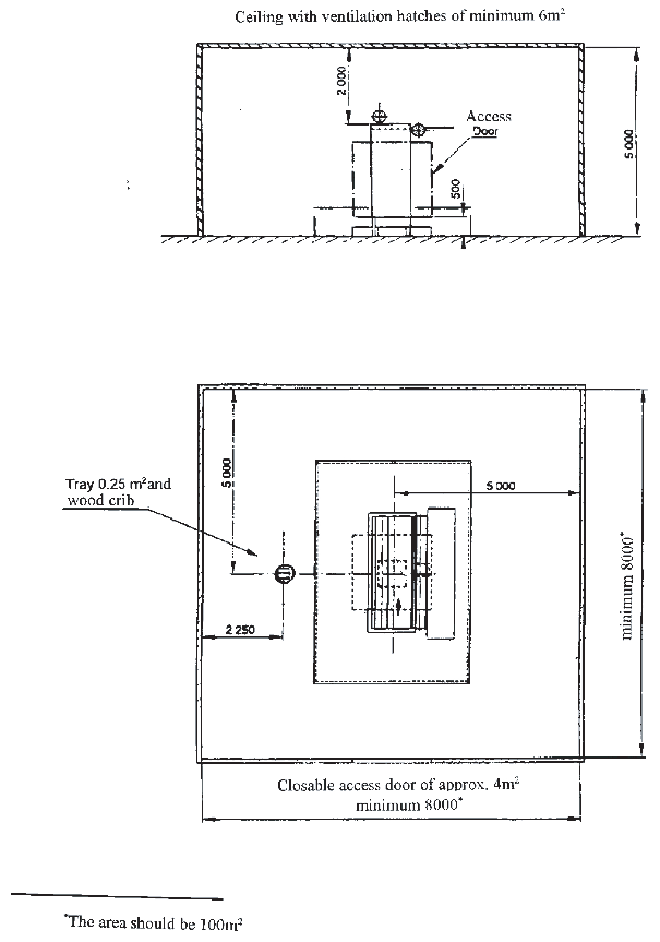
Figure 1
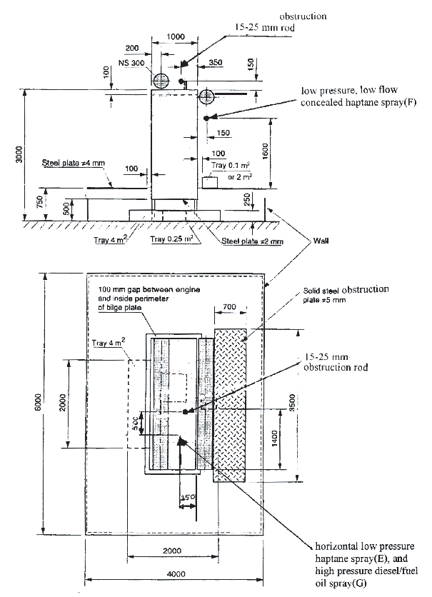
Figure 2
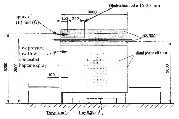
Figure 3
3.2.4 Instrumentation
Instrumentation for the continuous measurement and recording
of test conditions should be employed. The following measurements
should be made:
-
.1 temperature at three vertical positions (e.g.,
1, 2.5, and 4.5 m)
-
.2 enclosure pressure
-
.3 gas sampling and analysis, at mid-room height,
for oxygen, carbon dioxide, carbon monoxide, and relevant halogen
acid products, e.g., hydrogen iodide, hydrofluoric acid, hydrochloric
acid
-
.4 means of determining flame-out indicators
-
.5 fuel nozzle pressure in the case of spray fire
-
.6 fuel flow rate in the case of spray fires
-
.7 discharge nozzle pressure
3.2.5 Nozzles
-
3.2.5.1 For test purposes, nozzles should be located
within 1 m of the ceiling.
-
3.2.5.2 If more than one nozzle is used they should
be symmetrically located.
3.2.6 Enclosure temperature
The ambient temperature of the test enclosure at the start of
the test should be noted and serve as the basis for calculating the
concentration that the agent would be expected to achieve at that
temperature and with that agent weight applied in the test volume.
3.3 Test fires and programme
3.3.1 Fire types
The test programme, as described in table
3, should employ test fires as described in table 1.
Achieve ignition of the crib by burning commercial grade
heptane in a square steel tray 0.25 m2 in area. During
the pre-burn period the crib should be placed centrally above the
top of the tray a distance of 300 to 600 mm.
Table 1 Parameters of Test
Fires
| Parameters of Test Fires
|
| Fire
|
Type
|
Fuel
|
Fire Size,
MW
|
Remarks
|
| A
|
76–100 mm ID
can
|
Heptane
|
0.0012
to 0.002
|
Tell
tale
|
| B
|
0.25 m²
Tray
|
Heptane
|
0.35
|
|
| C
|
2 m² Tray
|
Diesel/Fuel
Oil
|
3
|
|
| D
|
4 m² Tray
|
Diesel/Fuel
Oil
|
6
|
|
| E
|
Low pressure
spray
|
Heptane 0.16 ± 0.01
kg/s
|
5.8
|
|
| F
|
Low pressure, low
flow spray
|
Heptane 0.03 ±
0.005 kg/s
|
1.1
|
|
| G
|
High pressure
spray
|
Diesel/Fuel Oil 0.05
± 0.002 kg/s
|
1.8
|
|
| H
|
Wood crib
|
Spruce or
Fir
|
0.3
|
See Note 2
|
| I
|
0.10 m²
Tray
|
Heptane
|
0.14
|
|
| Notes to Table 1:
|
|
|
| 1
|
Diesel/Fuel Oil means light diesel or
commercial fuel oil.
|
| 2
|
The wood crib should be substantially the same as described in
ISO/TC21/SC 5/WG 8 ISO Draft International Standard, Gaseous fire
extinguishing systems, Part 1: General Requirements. The crib should
consist of six, trade size 50 mm x 50 mm by 450 mm long, kiln dried
spruce or fir lumber having a moisture content between 9% and 13%. The
members should be placed in 4 alternate layers at right angles to one
another. Members should be evenly spaced forming a square
structure.
|
|
|
|
|
3.3.2 Test programme
The fire test programme should employ test fires singly or in
combination, as outlined in table 3.
-
3.3.2.1 All applicable tests of table 3 should be conducted for every
new fire extinguishant gas, or mixture of gases.
-
3.3.2.2 Only Test 1 is required to evaluate new
nozzles and related distribution system equipment (hardware) for systems
employing fire extinguishants that have successfully completed the
requirements of 3.3.2.1. Test 1 should be conducted to establish and
verify the manufacturer's minimum nozzle design pressure.
Table 2 Spray fire test
parameters
| Spray fire test parameters
|
| Fire Type
|
Low Pressure
(E)
|
Low pressure, Low
flow (F)
|
High pressure
|
| Spray
nozzle
|
Wide spray angle (120
to 125°) full cone type
|
Wide
spray angle (80°) full cone type
|
Standard angle (at 6 Bar) full cone type
|
| Nominal fuel
pressure
|
8 Bar
|
8.5 Bar
|
150 Bar
|
| Fuel flow
|
0.16 ± 0.01
kg/s
|
0.03 ± 0.005
kg/s
|
0.050 ± 0.002 kg/s
|
| Fuel
temperature
|
20 ± 5°C
|
20 ± 5°C
|
20 ± 5°C
|
| Nominal heat release
rate
|
5.8 ± 0.6 MW
|
1.1 ± 0.1 MW
|
1.8 ± 0.2 MW
|
Table 3 Test Programme
| Test Programme
|
| Test No.
|
Fire Combinations (See Table 1)
|
| 1
|
A:
|
Tell tales, 8 corners.
See note 1.
|
| 2–a
|
B:
|
0.25 m² heptane tray
under engine mock up
|
|
|
E:
|
Horizontal LP spray directed at 15–25 mm rod 0.5 m away
|
| See
Note 2
|
G:
|
HP
diesel fuel oil spray on top of engine mock up
|
|
|
|
Total
Fire Load: 0.49 MW
|
| 2–b
|
B:
|
0.25
m² heptane tray under mock up
|
|
|
I:
|
0.10
m² heptane tray on deck plate located below sold steel
|
| See
Note 2
|
|
obstruction plate.
|
|
|
|
Total
Fire Load: 0.49 MW
|
| 3
|
C:
|
2 m²
diesel/fuel oil tray on deck plate located below sold steel obstruction
plate
|
|
|
H:
|
Wood
crib positioned as in Figure 1
|
|
|
F:
|
Low
pressure, low flow horizontal spray — concealed — with impingement on
inside of engine mock-up wall.
|
|
|
|
Total
Fire Load: 4.4 MW
|
| 4
|
D:
|
4 m²
Diesel tray under engine mock-up
|
|
|
|
Total
Fire Load: 6 MW
|
| Notes to table 3:
|
|
| 1
|
Tell-tale fire cans should be located as
follows:
|
|
|
(a) in upper corners of enclosure 150 mm
below ceiling and 50 nn from each wall;
|
|
|
(b) in corners on floors 50mm from
walls.
|
| 2
|
Test 2–a is for use in evaluating
extinguishing systems having discharge times of 10 seconds or
less.
|
|
|
Test 2–b is for use in evaluating
extinguishing systems having discharge times greater than 10
seconds.
|
3.4 Extinguishing system
3.4.1 System installation
The extinguishing system should be installed according to the
manufacturer's design and installation instructions. The maximum vertical
distance should be limited to 5 m.
3.4.2 Agent
-
3.4.2.1 Design concentration
The agent design concentration is that concentration (in volume
per cent) required by the system designer for the fire protection
application.
-
3.4.2.2 Test concentration
The concentration of agent to be used in the fire extinguishing
tests should be the design concentration specified by the extinguishing
system manufacturer, except for Test 1 which should be conducted at
77% of the manufacturer's recommended design concentration but in
no case at less than the cup burner extinguishing concentration.
-
3.4.2.3 Quantity of agent
The quantity of agent to be used should be determined as follows:
3.5 Procedure
3.5.1 Fuel levels in trays
The trays used in the test should be filled with at least 30
mm fuel on a water base. Freeboard should be 150 ± 10 mm.
3.5.2 Fuel flow and pressure measurements
For spray fires, the fuel flow and pressure should be measured
before and during each test.
3.5.3 Ventilation
-
3.5.3.1 Pre-burn period
During the pre-burn period the test enclosure should be well
ventilated. The oxygen concentration, as measured at mid-room height,
shall not be less than 20 volume per cent at the time of system discharge.
-
3.5.3.2 End of pre-burn period
Doors, ceiling hatches, and other ventilation openings should
be closed at the end of the pre-burn period.
3.5.5 Measurements and observations
-
3.5.5.1 Before test
-
.1 temperature of test enclosure, fuel and engine
mock-up
-
.2 initial weights of agent containers
-
.3 verification of integrity agent distribution
system and nozzles
-
.4 initial weight of wood crib.
-
3.5.5.2 During test
-
.1 start of the ignition procedure
-
.2 start of the test (ignition)
-
.3 time when ventilating openings are closed
-
.4 time when the extinguishing system is activated
-
.5 time from end of agent discharge
-
.6 time when the fuel flow for the spray fire
is shut off
-
.7 time when all fires are extinguished
-
.8 time of re-ignition, if any, during soak period
-
.9 time at end of soak period
-
.10 at the start of test initiate continuous monitoring
as per 3.2.4.
3.5.6 Tolerances
Unless otherwise stated, the following tolerances should apply:
| .1
|
length
|
±2 % of
value
|
| .2
|
volume
|
±5 % of
value
|
| .3
|
pressure
|
±3 % of
value
|
| .4
|
temperature
|
±5 % of
value
|
| .5
|
concentration
|
±5 % of
value.
|
These tolerances are in accordance with ISO standard 6182/1,
February 1994 edition [4].
|
| Copyright 2026 Clasifications Register Group Limited, International Maritime Organization, International Labour Organization or Maritime
and Coastguard Agency. All rights reserved. Clasifications Register Group Limited, its affiliates and subsidiaries and their respective
officers, employees or agents are, individually and collectively, referred to in this clause as 'Clasifications Register'. Clasifications
Register assumes no responsibility and shall not be liable to any person for any loss, damage or expense caused by reliance
on the information or advice in this document or howsoever provided, unless that person has signed a contract with the relevant
Clasifications Register entity for the provision of this information or advice and in that case any responsibility or liability is
exclusively on the terms and conditions set out in that contract.
|
 |
|