Goal
To protect cargo containment systems from harmful overpressure or underpressure
at all times.
8.1 General
All cargo tanks shall be provided with a pressure relief system
appropriate to the design of the cargo containment system and the cargo being
carried. Hold spaces and interbarrier spaces, which may be subject to pressures
beyond their design capabilities, shall also be provided with a suitable pressure
relief system. Pressure control systems specified in chapter 7 shall be independent
of the pressure relief systems.
8.2
Pressure relief systems
8.2.1 Cargo tanks, including deck tanks, shall be
fitted with a minimum of two pressure relief valves (PRVs), each being of equal size
within manufacturer's tolerances and suitably designed and constructed for the
prescribed service.
8.2.2 Interbarrier spaces shall be provided with
pressure relief devicesfootnote. For membrane systems, the designer shall demonstrate
adequate sizing of interbarrier space PRVs.
8.2.3 The setting of the PRVs shall not be higher than
the vapour pressure that has been used in the design of the tank. Where two or more
PRVs are fitted, valves comprising not more than 50% of the total relieving capacity
may be set at a pressure up to 5% above MARVS to allow sequential lifting,
minimizing unnecessary release of vapour.
8.2.4 The following temperature requirements apply to
PRVs fitted to pressure relief systems:
-
.1 PRVs on cargo tanks with a design
temperature below 0°C shall be designed and arranged to prevent their
becoming inoperative due to ice formation;
-
.2 the effects of ice formation due to ambient
temperatures shall be considered in the construction and arrangement of
PRVs;
-
.3 PRVs shall be constructed of materials with
a melting point above 925°C. Lower melting point materials for internal
parts and seals may be accepted, provided that fail-safe operation of the
PRV is not compromised; and
-
.4 sensing and exhaust lines on pilot operated
relief valves shall be of suitably robust construction to prevent
damage.
8.2.5
Valve testing
8.2.5.1 PRVs shall be type-tested. Type tests shall
include:
-
.1 verification of relieving capacity;
-
.2 cryogenic testing when operating at design
temperatures colder than -55°C;
-
.3 seat tightness testing; and
-
.4 pressure containing parts are pressure
tested to at least 1.5 times the design pressure.
PRVs shall be tested in accordance with recognized standardsfootnote.
8.2.5.2 Each PRV shall be tested to ensure that:
-
.1 it opens at the prescribed pressure setting,
with an allowance not exceeding ± 10% for 0 to 0.15 MPa, ± 6% for 0.15 to
0.3 MPa, ± 3% for 0.3 MPa and above;
-
.2 seat tightness is acceptable; and
-
.3 pressure containing parts will withstand at
least 1.5 times the design pressure.
LR 8.2-01 Where the APBU notation is to be assigned, the
details of the method and means of achieving equalisation between the interbarrier
space and cargo tank are to be submitted.
8.2.6 PRVs shall be set and sealed by the
Administration or recognized organization acting on its behalf, and a record of this
action, including the valves' set pressure, shall be retained on board the ship.
LR 8.2-02 As soon as practicable prior to proceeding on gas
trials, pressure relief valves are to be tested and installed in accordance with the
manufacturer’s recommended procedures to the Surveyor’s satisfaction. Where valves
are stored prior to installation on board, the storage arrangements are also to be
in accordance with the manufacturer’s recommended procedures.
8.2.7 Cargo tanks may be permitted to have more than
one relief valve set pressure in the following cases:
-
.1 installing two or more properly set and
sealed PRVs and providing means, as necessary, for isolating the valves not
in use from the cargo tank; or
-
.2 installing relief valves whose settings may
be changed by the use of a previously approved device not requiring pressure
testing to verify the new set pressure. All other valve adjustments shall be
sealed.
8.2.8 Changing the set pressure under the provisions of
8.2.7 and the corresponding resetting of the alarms referred to in 13.4.2 shall be
carried out under the supervision of the master in accordance with approved
procedures and as specified in the ship's operating manual. Changes in set pressure
shall be recorded in the ship's log and a sign shall be posted in the cargo control
room, if provided, and at each relief valve, stating the set pressure.
8.2.9 In the event of a failure of a cargo
tank-installed PRV, a safe means of emergency isolation shall be available:
-
.1 Procedures shall be provided and included in
the cargo operations manual (see 18.2).
-
.2 The procedures shall allow only one of the
cargo tank installed PRVs to be isolated.
-
.3 Isolation of the PRV shall be carried out
under the supervision of the master. This action shall be recorded in the
ship's log and a sign posted in the cargo control room, if provided, and at
the PRV.
-
.4 The tank shall not be loaded until the full
relieving capacity is restored.
LR 8.2-03 The ‘safe means of emergency isolation’, as required by
8.2.9, is to be provided so that a PRV can be isolated on a temporary basis to
reseat or repair the valve before putting the PRV back into service. Such means of
emergency isolation are to be installed in a manner that does not allow their
inadvertent operation.
8.2.10 Each PRV installed on a cargo tank shall be
connected to a venting system, which shall be:
-
.1 so constructed that the discharge will be
unimpeded and directed vertically upwards at the exit;
-
.2 arranged to minimize the possibility of
water or snow entering the vent system;
-
.3 arranged such that the height of vent exits
shall not be less than B/3 or 6 m, whichever is the greater, above the
weather deck; and
-
.4 6 m above working areas and walkways.
8.2.11.1 Cargo PRV vent exits shall be arranged at a
distance at least equal to B or 25 m, whichever is less, from the nearest air
intake, outlet or opening to accommodation spaces, service spaces and control
stations, or other non-hazardous areas. For ships less than 90 m in length, smaller
distances may be permitted.
8.2.11.2 All other vent outlets connected to the cargo
containment system shall be arranged at a distance of at least 10 m from the nearest
air intake, outlet or opening to accommodation spaces, service spaces and control
stations, or other non-hazardous areas.
8.2.12 All other cargo vent outlets not dealt with in
other chapters shall be arranged in accordance with 8.2.10, 8.2.11.1 and 8.2.11.2.
Means shall be provided to prevent liquid overflow from vent mast outlets, due to
hydrostatic pressure from spaces to which they are connected.
8.2.13 If cargoes that react in a dangerous manner with
each other are carried simultaneously, a separate pressure relief system shall be
fitted for each one.
8.2.14 In the vent piping system, means for draining
liquid from places where it may accumulate shall be provided. The PRVs and piping
shall be arranged so that liquid can, under no circumstances, accumulate in or near
the PRVs.
8.2.15 Suitable protection screens of not more than 13
mm square mesh shall be fitted on vent outlets to prevent the ingress of extraneous
objects without adversely affecting the flow. Other requirements for protection
screens apply when carrying specific cargoes (see 17.9 and 17.21).
8.2.16 All vent piping shall be designed and arranged
not to be damaged by the temperature variations to which it may be exposed, forces
due to flow or the ship's motions.
8.2.17 PRVs shall be connected to the highest part of
the cargo tank above deck level. PRVs shall be positioned on the cargo tank so that
they will remain in the vapour phase at the filling limit (FL) as defined in
chapter 15, under conditions of 15° list and 0.015L trim, where L is defined in
1.2.31.
8.2.18 The adequacy of the vent system fitted on tanks
loaded in accordance with 15.5.2 shall be demonstrated, taking into account the
recommendations developed by the Organizationfootnote. A relevant certificate shall be
permanently kept on board the ship. For the purposes of this paragraph, vent system
means:
-
.1 the tank outlet and the piping to the
PRV;
-
.2 the PRV; and
-
.3 the piping from the PRVs to the location of
discharge to the atmosphere, including any interconnections and piping that
joins other tanks.
8.3 Vacuum protection systems
8.3.1 Cargo tanks not designed to withstand a maximum
external pressure differential 0.025 MPa, or tanks that cannot withstand the maximum
external pressure differential that can be attained at maximum discharge rates with
no vapour return into the cargo tanks, or by operation of a cargo refrigeration
system, or by thermal oxidation, shall be fitted with:
-
.1 two independent pressure switches to
sequentially alarm and subsequently stop all suction of cargo liquid or
vapour from the cargo tank and refrigeration equipment, if fitted, by
suitable means at a pressure sufficiently below the maximum external
designed pressure differential of the cargo tank; or
-
.2 vacuum relief valves with a gas flow
capacity at least equal to the maximum cargo discharge rate per cargo tank,
set to open at a pressure sufficiently below the external design
differential pressure of the cargo tank.
8.3.2 Subject to the requirements of chapter 17, the
vacuum relief valves shall admit an inert gas, cargo vapour or air to the cargo tank
and shall be arranged to minimize the possibility of the entrance of water or snow.
If cargo vapour is admitted, it shall be from a source other than the cargo vapour
lines.
LR 8.3–01 Vacuum relief valves are not to admit air to the cargo
tanks except where satisfactory controls, low pressure alarms and automatic devices
for stopping cargo pumps and compressors, etc., are fitted and adjusted such that
the pressure in the tanks cannot fall below a predetermined minimum safe level.
Details are to be submitted for consideration.
8.3.3 The vacuum protection system shall be capable of
being tested to ensure that it operates at the prescribed pressure.
8.4
Sizing of pressure relieving system
8.4.1
Sizing of pressure relief valves
PRVs shall have a combined relieving capacity for each cargo tank to
discharge the greater of the following, with not more than a 20% rise in cargo tank
pressure above the MARVS:
8.4.1.1 The maximum capacity of the cargo tank inerting
system, if the maximum attainable working pressure of the cargo tank inerting system
exceeds the MARVS of the cargo tanks; or
8.4.1.2 Vapours generated under fire exposure computed
using the following formula:
-
Q = FGA0.82
(m3/s),
-
where:
-
|
Q
|
= |
minimum required rate of discharge of air at
standard conditions of 273.15 Kelvin (K) and 0.1013 MPa; |
-
|
F
|
= |
fire exposure factor for different cargo types as
follows: |
-
– 1 for tanks without insulation located on deck;
-
– 0.5 for tanks above the deck, when insulation is
approved by the Administration. Approval will be based on the
use of a fireproofing material, the thermal conductance of
insulation and its stability under fire exposure;
-
– 0.5 for uninsulated independent tanks installed in
holds;
-
– 0.2 for insulated independent tanks in holds (or
uninsulated independent tanks in insulated holds);
-
– 0.1 for insulated independent tanks in inerted
holds (or uninsulated independent tanks in inerted, insulated
holds);
-
– 0.1 for membrane and semi-membrane tanks. For
independent tanks partly protruding through the weather decks,
the fire exposure factor shall be determined on the basis of the
surface areas above and below deck.
-
|
G
|
= |
gas factor according to formula: |
LR 8.4-01 For prismatic tanks Lmin, and the
associated external surface area of the tank, A, are to be taken as
follows:
See Figure 8.1
8.4.1.3 The required mass flow of air at relieving
conditions is given by the formula:
Mair
= Q ρair
(kg/s),
where:
- density of air(ρair
) = 1.293 kg/m3 (air at 273.15 K, 0.1013 MPa).
8.4.2
Sizing of vent pipe system
Pressure losses upstream and downstream of the PRVs shall be taken into
account when determining their size to ensure the flow capacity required by
8.4.1.
8.4.3
Upstream pressure losses
8.4.3.1 The pressure drop in the vent line from the
tank to the PRV inlet shall not exceed 3% of the valve set pressure at the
calculated flow rate, in accordance with 8.4.1.
8.4.3.2 Pilot-operated PRVs shall be unaffected by
inlet pipe pressure losses when the pilot senses directly from the tank dome.
8.4.3.3 Pressure losses in remotely sensed pilot lines
shall be considered for flowing type pilots.
8.4.4
Downstream pressure losses
8.4.4.1 Where common vent headers and vent masts are
fitted, calculations shall include flow from all attached PRVs.
8.4.4.2 The built-up back pressure in the vent piping
from the PRV outlet to the location of discharge to the atmosphere, and including
any vent pipe interconnections that join other tanks, shall not exceed the following
values:
-
.1 for unbalanced PRVs: 10% of MARVS;
-
.2 for balanced PRVs: 30% of MARVS; and
-
.3 for pilot operated PRVs: 50% of MARVS.
Alternative values provided by the PRV manufacturer may be accepted.
8.4.5 To ensure stable PRV operation, the blow-down
shall not be less than the sum of the inlet pressure loss and 0.02 MARVS at the
rated capacity.
LR 8.4-02
Sizing of pressure relief valves for hold and interbarrier spaces
LR 8.4-03 The relieving capacity formula given in paragraph LR 8.4-09 is
developed for interbarrier spaces surrounding independent type A cargo tanks.
LR 8.4-04 The relieving capacity of pressure relief devices of interbarrier
spaces surrounding independent type B cargo tanks may be determined on the basis of
the method given in paragraph 8.4-09; however, the leakage rate is to be determined
in accordance with section 4.7.2.
LR 8.4-05 The relieving capacity of pressure relief devices for interbarrier
spaces of membrane and semi-membrane tanks is to be evaluated on the basis of the
specific membrane/semi-membrane tank design.
LR 8.4-06 The relieving capacity of pressure relief devices for interbarrier
spaces adjacent to integral type cargo tanks may, if applicable, be determined as
for independent type A cargo tanks.
LR 8.4-08 The combined relieving capacity of the pressure relief devices for
interbarrier spaces surrounding independent type A cargo tanks where the insulation
is fitted to the cargo tanks may be determined by the following
formula:
|
Qsa |
= |
minimum required discharge rate of air at standard conditions of 273,15
K and 1,013 bar (m3/s) |
|
Ac |
= |
Design crack opening area (m2) |
|
δ |
= |
maximum crack opening width (m) |
|
δ |
= |
0,2t (m) |
|
t |
= |
thickness of tank bottom plating (m) |
|
l |
= |
design crack length (m) equal to the diagonal of the largest plate panel
of the tank bottom, see Figure LR 8.2 below. |
|
h |
= |
max liquid height above tank bottom plus 10 x MARVS (m) |
|
ρ |
= |
density of product liquid phase (kg/m3) at the set pressure
of the interbarrier space relief device |
|
ρv |
= |
= density of product vapour phase (kg/m3) at the set pressure
of the interbarrier space relief device and a temperature of 273,15 K |
|
MARVS |
= |
max allowable relief valve setting of the cargo tank (bar) |
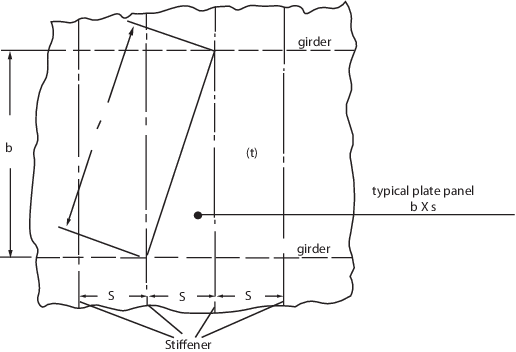
Figure LR 8.2 Design Crack