1 Scope and field of application
This appendix gives directions for measuring nominal air change and air distribution in
connection with testing of ventilation plants in ro-ro ship's cargo spaces where running
of vehicles with internal combustion engines occurs.
The nominal air change is measured by calculation of the air flow in supply air and
exhaust air terminal devices. The air distribution is normally estimated visually with
visible smoke, or by measuring with tracer gas.
2 Nominal air change
In order to verify that the calculated quantity of air is supplied to the ro-ro cargo
spaces, the air flow rate should be measured in each supply air and, where appropriate,
exhaust air terminal device.
2.1 Instruments for Measurement of Air Flow
Although alternative techniques, such as the pilot traverse method are available,
anemometers are generally employed for low velocity air flow measurements. There are two
general types of anemometers:
-
.1 The direct-reading anemometer of the electronic type which registers the air
velocity almost instantaneously. This has a distinct non-uniform airflow as any
instability or random changes of velocity are immediately seen and the true mean
of the velocity at a point can be judged. It is also very quick to use.
-
.2 The mechanical type of direct reading anemometer with a rotating vane. The
movement is a rotary deflection against the action of a spring.
These types of anemometer are small and compact, easy to read and use, give reasonably
steady readings and any fault or inconsistency developing is usually quite apparent.
Where a correction chart is supplied with an anemometer the correction factors should be
applied to the measured velocities before comparing them. With a good quality instrument
in proper repair used by an experienced operator, the probable error on the comparative
value obtained will range from a maximum of ± 2% when comparing similar velocities to a
maximum of ± 5% when comparing widely differing velocities.
2.2 Air Flow Measurement Procedurefootnote
For supply or extract grilles the anemometer is used as follows:
The gross grille area is divided into 150-300 mm squares, depending upon the size of
grille and variation in the velocity pattern.
The anemometer is held at the centre of each square with the back of the instrument
touching the louvres which should be set without deflection. The instrument will give an
immediate reading of the indicated velocity at each square and this reading should be
recorded. When the indicated velocities at the centre of all squares have been recorded,
the average value of these velocities should be calculated; this average value should be
taken as the "indicated velocity" for the whole grille.
This method will normally provide repeatable results. In practice the only inconsistency
which is necessary to consider appears where the grille damper is well closed down,
causing the air to strike the anemometer vanes in separate jets rather than with uniform
velocity. In this case a hood may have to be used with the anemometer.
2.3 Calculations
The air flow rate at each supply-extract grille is calculated as follows:
The global rate of air change per hour achieved by the vehicle deck system(s) is
subsequently calculated as follows:
2.4 Report
A report should be drawn up in accordance with paragraph 4 of this appendix.
3 Air distribution
3.1 Visual study with visible smoke
In order to assess air change rate the movement of air and the existence of poorly
ventilated areas, visible smoke can be released into the space. With the ventilation
system operating, the movement of air and the dissipation of smoke can be studied and
the air change rate estimated.
3.2 Measurement with tracer gas
By use of tracer gas it is possible to estimate air change rate and air distribution in
chosen points in the ro-ro cargo space.
Measurement with tracer gas involves mixing a gaseous component with the air. The
atmosphere in the space is examined to determine how dilution of the tracer gas is
tracked at chosen points in the ro-ro cargo space whilst the ventilation system is
operational.
This method should be carried out with and without vehicles.
3.2.1 Test procedures
The placing of the measurement probes should be chosen with regard to the purpose of the
measurement. The probes are not to be placed near to the supply air terminal devices or
at places where a so-called ventilation shadow can be expected, such as behind pillars,
webs, etc. As a rule the probes are placed at the head height and in the vicinity of
persons working on the deck.
The tracer gas should be spread and mixed in the air as completely as possible. The
mixing may be done by the ordinary ventilation plant or with help of external fans. In
order to reach an adequate accuracy, the concentration of the tracer gas ought to reach
at least 50 times the detection limit of the analytical instrumentation.
When the tracer gas concentration is adequate the ventilation plant as well as the
measurement equipment should be started. Tracer gas concentration should be recorded
until the detection level is reached.
3.2.2 Calculation
With a dilution ventilation system the logarithm of the concentration of tracer gas will
be linear with regard to time (see figure 1 below).
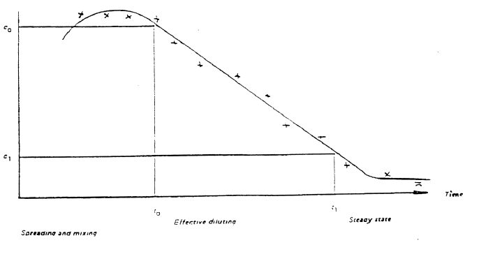
Figure 1 – The logarithm of the concentration of tracer gas
The relation between the concentration of tracer gas and time (the inclination of the
graph) is a straight measure of the effect to the ventilation expressed in number of air
changes according to the following formula:
where
|
N |
= |
number of changes |
|
c0 |
= |
the concentration at the beginning of the effective dilution |
|
c1 |
= |
the concentration at the end of the effective dilution |
|
t0 |
= |
the point of time at the beginning of the effective dilution |
|
t1 |
= |
the point of time at the end of the effective dilution |
3.3 Alternatives
As an alternative to the tests in paragraphs 3.1 and 3.2, air flow distribution in the
ro-ro cargo space may be evaluated by use of an anemometer; or
The air flow can be determined by means of a calculation based methodology (such as
Computational Fluid Dynamics and/or the use of established empiric formulae) to be
accepted by the Administration.
4 Report
A written report should be provided containing the following information:
| Ship's data
|
including ship name, register,
number, length, breadth, draught, GT, owner, shipyard, name of
contractor carrying out the test.
|
| Weather conditions
|
Wind speed and direction in general and in
relation to the longitudinal of the ship during measurements.
|
| Veichle deck measurements
|
Deck length, breadth, height, and
volume.
|
| Ventilation
|
A plan of the deck indicating the location of
supply and exhaust fans, together with information on grille surface
area, design capacity and actual capacity of each unit. The use of
additional air mixing equipment (e.g. dirivent) should also be noted. An
indication of the status of all other openings to the deck during
sampling should also be provided.
|
| Activity
|
Details of loading and unloading should be
included. These should comprise the time taken for each
loading/unloading operation, the number of personnel working, the number
and type of vehicles present.
|
| Measurements
|
Time and date of the measurements
- Instrumentation
- Calibration
- Measurement procedure
- Sample locations
- Details of sample analysis
|
| Results
|
Measurement results
Calculation of
occupational exposure
|
5 Conclusions/Recommendations
In addition to the statement of results the report should contain a plan of the ro-ro
cargo space with supply air and exhaust air ducts shown. Where appropriate, the
measurement points, type and number of vehicles, etc. should be indicated. Notes should
be made regarding circumstances that affect the ventilation systems and/or air flow
patterns on the deck.
When conducting a visual study with visible smoke, a detailed description of discharge
and dissipation of the smoke as well as lapse of time should be given.