
7.5 Positioning of Thermocouples
on the Specimen
7.5.1 "A" class divisions, excluding doors
The surface temperatures on the unexposed face of the test
specimen should be measured by thermocouples located as shown in Figures 7 and 8:
-
.1 five thermocouples, one at the centre of the
test specimen and one at the centre of each of the four quarters,
all positioned at least 100 mm away from the nearest part of any joints
and/or at least 100 mm away from the welds to any stiffeners;
-
.2 two thermocouples, one placed over each of
the central stiffeners and for a bulkhead at 0.75 height of the specimen
and for a deck at mid-length of the deck;
-
.3 two thermocouples, each placed over a vertical
(longitudinal) joint, if any, in the insulation system and positioned
for a bulkhead at 0.75 height of the specimen and for a deck at mid-length
of the deck;
-
.4 when a construction has two differently orientated
joint details, for example normal to each other, then two thermocouples
additional to those already described in 7.5.1.3 above should be used,
one on each of two intersections;
-
.5 when a construction has two different types
of joint detail, then two thermocouples should be used for each type
of joint;
-
.6 additional thermocouples, at the discretion
of the testing laboratory or Administration, may be fixed over special
features or specific construction details if it is considered that
temperatures higher than those measured by the thermocouples listed
above may result; and
-
.7 the thermocouples specified in 7.5.1.4 to 7.5.1.6
above for measurements on bulkheads, e.g. over different joint types
or over joint intersections, should, where possible, be positioned
in the upper half of the specimen.
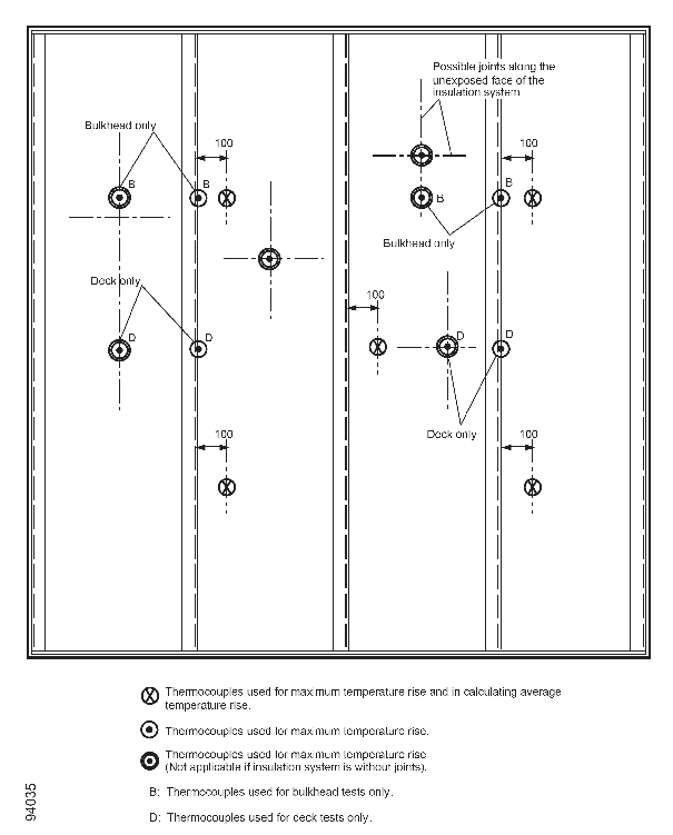
Figure 7 Position of unexposed-face thermocouples for `A' class division:
insulated face to the laboratory
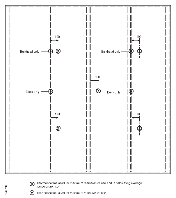
Figure 8 Position of unexposed-face thermocouples for `A' class division: flat
face of structural steel core to the laboratory
7.5.2 "B" and "F" class divisions, excluding doors
The surface temperatures on the unexposed face of the test
specimen should be measured by thermocouples located as shown in Figure 9:
-
.1 five thermocouples, one at the centre of the
test specimen and one at the centre of each of the four quarters,
all positioned at least 100 mm away from the nearest part of any joints;
-
.2 two thermocouples, each placed over a vertical
(longitudinal) joint, if any, in the division/insulation system and
positioned for a bulkhead at 0.75 height of the specimen and for a
deck/ceiling at mid-length of the deck/ceiling; and
-
.3 additional thermocouples, as required by 7.5.1.4
to 7.5.1.7 above.
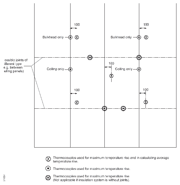
Figure 9 Position of unexposed-face thermocouples for `B' and `F' class
divisions
7.5.3 "A", "B" and "F" class doors
The surface temperatures on the unexposed face of the test
specimen should be measured by:
-
.1 five thermocouples, one at the centre of the
door leaf and one at the centre of each of the four quarters of the
door leaf, all positioned at least 100 mm away from the edge of the
door leaf, from any stiffeners, from any door furniture and from any
special features or specific constructional details;
-
.2 if the door leaf incorporates stiffeners, two
additional thermocouples, one placed over each of two stiffeners in
the central portion of the door;
-
.3 additional thermocouples, at the discretion
of the testing laboratory or Administration, may be fixed over special
features or specific constructional details if it is considered that
temperatures higher than those measured by the thermocouples listed
above may result. Any additional thermocouples fixed to the door frame,
or to any part of the door leaf, which is closer than a distance of
100 mm from the gap between the edge of the door leaf and the frame
should not be used for the purpose of classification of the test specimen,
and if provided are for information only;
-
.4 the thermocouples specified in 7.5.3.2 and
7.5.3.3 above should, where possible, be positioned in the upper half
of the specimen; and
-
.5 when testing double-leaf door assemblies, the
requirements should be applied to each door leaf separately.
|
| Copyright 2022 Clasifications Register Group Limited, International Maritime Organization, International Labour Organization or Maritime
and Coastguard Agency. All rights reserved. Clasifications Register Group Limited, its affiliates and subsidiaries and their respective
officers, employees or agents are, individually and collectively, referred to in this clause as 'Clasifications Register'. Clasifications
Register assumes no responsibility and shall not be liable to any person for any loss, damage or expense caused by reliance
on the information or advice in this document or howsoever provided, unless that person has signed a contract with the relevant
Clasifications Register entity for the provision of this information or advice and in that case any responsibility or liability is
exclusively on the terms and conditions set out in that contract.
|
 |
|