By 2.1
Figure 1 is a simplified flow sheet
of a cargo tank vent system with one vent stack connected to two tanks.
The system has been divided into sections between nodes, marked by
capital letters A to N, at changes in pipe diameter and at interconnections
with flows from other relief valves at F and J.
Table 1 lists the vent
pipe lengths and external surfaces areas, the fittings in the vent
system and their Friction Resistance Factors. Table 2 gives some typical values
for Friction Resistance Factors (N). N may vary with pipe diameter.
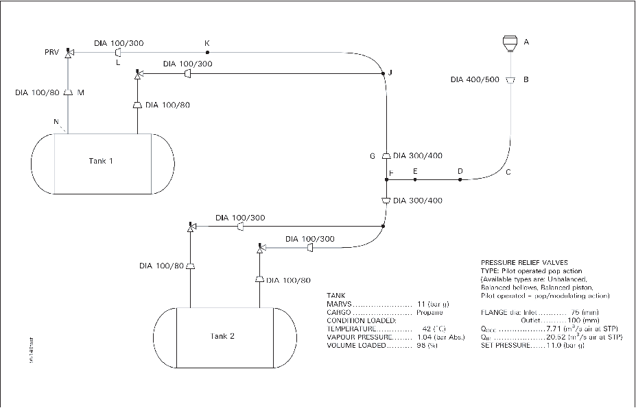
Figure 1 Simplified Flow Sheet of a Cargo Tank Vent System With One Vent Stack
Connected Two Tanks
Table 1 List of Vent Pipe Lengths
and Surface Areas, Fittings and Dynamic Loss Coefficients
| Pipe section
|
Length
(mm)
|
Pipe
Diameter (mm)
|
Surface
area (m2)
|
Fitting
|
Specification
|
Dynamic
loss coefficients N
|
Pipe
|
|
| A
|
1,080
|
500/750
|
2.04
|
A =
Cowl/Vent Exit
|
—
|
2.25
|
—
|
2.25
|
| A-B
|
1,565
|
500
|
2.46
|
|
|
|
0.063
|
0.063
|
| Section
total
|
|
|
4.50
|
|
|
|
|
2.313
|
| B-C
|
2,650
|
400
|
3.331
|
B = Conical
Expansion
|
d/D =
0.8
|
*
|
0.132
|
0.132
|
| C-D
|
2,546
|
400
|
3.20
|
C = Long
Radius Bend
|
90°
|
0.3
|
0.127
|
0.427
|
| D-E
|
14,880
|
400
|
18.701
|
D = Bend
|
45°
|
0.2
|
0.744
|
0.944
|
| E-F
|
2,093
|
400
|
2.63
|
E =
Bend
|
45°
|
0.2
|
0.105
|
0.305
|
| Section
total
|
|
|
27.86
|
|
|
|
|
2.008
|
| F-G
|
642
|
400
|
0.81
|
F =Hard
Tee
|
—
|
1.1
|
0.032
|
1.132
|
| G-J
|
1,066
|
300
|
1.00
|
G = Conical
Expansion
|
d/D =
0.75
|
*)
|
0.071
|
0.071
|
| Section
total
|
|
|
1.81
|
|
|
|
|
|
| J-K
|
1,340
|
300
|
1.263
|
J = Soft
Tee
|
—
|
0.3
|
0.089
|
0.389
|
| K-L
|
481
|
300
|
0.453
|
K =
Bend
|
45°
|
0.2
|
0.032
|
0.232
|
| Section
total
|
|
|
1.72
|
|
|
|
|
0.621
|
| L-PRV
|
216
|
300/100
|
—
|
L =
Conical Expansion
|
d/D =
0.33
|
*
|
0.043
|
0.043
|
| PRV-M
|
108
|
80
|
—
|
|
|
|
0.027
|
0.027
|
| M
|
108
|
80
|
—
|
M =
Conical Expansion
|
d/D =
0.8
|
0.1
|
—
|
0.1
|
| M-N
|
142
|
80
|
—
|
N =
Square Edged Inlet
|
—
|
0.5
|
0.028
|
0.528
|
Table 2 Typical values for Dynamic
Loss Coefficient (N) for vent system fittings, 'N' may vary with pipe
diameter
|
Fitting
|
Equivalent
|
|
Inlet pipe from tank to PRV:
|
|
| Square-edged
inlet
|

|
0.5
|
| Protruding
conical inlet
|

|
0.15
|
| Conical
reduction
|

|
0.1
|
|
Discharge piping from PRV to mast vent exit:
|
|
| 45°
|
|
0.2
|
| 45°
single-mitre elbow
|
|
0.45
|
| 90°
|
|
0.3
|
| 90°
|
|
0.5
|
| 90°
|
|
0.6
|
| Soft-Tee
|

|
0.3
|
| Hard-Tee
|

|
1.1
|
| Cowi mast
vent exit
|

|
2.25
|
| Top-Hat
mast vent exit
|

|
[4.5]
|
| Flame
screen for IGC Code 17.10
|
|
1.4
|
| References:
|
| “Sizing Safety Valve Inlet Lines” Chemical
Engineering Process, November 1980
|
| “Engineering Data Book, Figure 17–4” Gas
processors Association, 10th Edition. 1987
|
| “Guide for Pressure-Relieving and Depressurising
Systems” Table 5, API RP 521 Third Edition, November 1990
|
By 2.2
The IGC Code minimum
tank relief capacity, QGCC
, is calculated
for the Case Study ship tank analysed in BCH 20/7, annexes 2 to 5
which has an external surface area 747 m2 MARVS 11.0 bar
g.
By IGC Code 8.5.2
for propane:
The QGCC
for actual case study ship
tank = 7.71 m3/s of Air at STP.
The installed rated capacity for two 75 mm
× 100 mm AGCo Type 95 POPRVs
QIR
= 20.52 m3/ s of
Air at standard conditions (STP) of 273 K and 1.013 bar a,
or 20.52/7.71 = 2.66 times the QGCC
By equation (1) for
all vapour mass flow rate
from tank for propane:
where hfg at
1.2 × MARVS=
308600 J/kg
or Code PRV all vapour mass flow rate per PRV = 5.22 kg/s
and Installed Rated all vapour mass flow rate per PRV =
5.22 × 2.66 = 13.89 kg/s
where hfg at MARVS =
322800 J/kg
or Installed Rated all vapour mass flow rate per PRV = 4.99
× 2.66 = 13.27 kg/s
By equation (2) for
two-phase mass flux
through PRV orifice for propane
At 1.2 MARVS where C = 2931 J/kg
At MARVS where C = 2750 J/kg
By equation (3) for
two-phase mass flow rate
through installed rated PRV orifice
area
Av
= 0.004032 m2;
Kw
= 0.72
W = 9727 × 0.72 × 0.004032 = 28.25 kg/s
w = 8959 × 0.72 ×0.004032 = 26.01 kg/s
By equation (4) for
two-phase mass flow rate
through Code PRV
By 2.3
The all
vapour capacity and two-phase pressure drops in the pipe from the
cargo tank to the PRV inlet are calculated as the difference in stagnation
pressures by suing the second term of equation
(5) for the pipe sections of constant diameter and by using equation (5.1) for conical reduction
fittings (contractions).
For Code PRV all vapour capacity at 1.2 × MARVS
Conical reduction fitting M:
Section N to PRV total ΔP = 0.039
+ 0.018 + 0.005 = 0.06 bar
For installed rated all vapour capacity at MARVS
Conical reduction fitting M:
Section N to PRV total ΔP = 0.295
+ 0.137 + 0.037 = 0.47 bar
For Code PRV two-phase capacity at 1.2 × MARVS
Conical reduction fitting M
Section N to PRV total ΔP = 0.01
+ 0.005 + 0.001 = 0.016 bar
For Installed Rated two-phase capacity at MARVS
Conical reduction fitting M:
Section N to PRV total ΔP = 0.06
+ 0.028 + 0.008 = 0.10 bar:
By 2.4
Check system
compliance with requirements of General Section ref. 1.3
-
1.3.1
At
Code PRV all vapour capacity at 1.2 × MARVS
ΔP× 100/P
MARVS =
0.06 × 100/11.0 = 0.55%
Guideline 1.3 = 3% maximum
At Code PRV two-phase capacity at 1.2 × MARVS
= 0.016 × 100/11.0 = 0.15%
-
1.3.2
At
installed rated all vapour capacity at MARVS
= 0.47 × 100/11.0 = 4.27%*
At installed rated two-phase capacity at MARVS
= 0.10 × 100/11.0 = 0.91%
-
* Acceptable because pilot senses at a point that
is not affected by the inlet pipe pressure drop. If a protruding conical
inlet (N= 0.15) had been added to the square-edged inlet (N= 0.5),
the pressure drop would have been reduced, by 0.15/0.5 × 29500
= 8900 Pa to 3800 Pa which is 3.5% of set
pressure.
|
ΔPclose
|
= |
>
0.02 × PMARVS + ΔPinlet
|
|
|
= |
> 0.02 × 11.0 + 0.47 > 0.69 bar
|
For stable operation of the PRV, closing pressure
should be less than:
11.0 - 0.69 ≤ 10.31 bar g for a pop-action POPRV
By 2.5
The two-phase
critical exit choking pressure is estimated, using saturated propane
properties at 1.2 ×MARVS (14.2 bar a)
and where W' for Code discharge from four PRVs
Thus the exit flow is not choked and the vent pipe exit
pressure is 100000 Pa (1 bar a)
By 2.6
The exit
vapour fraction, xe
, assuming a fire exposure
heat flux of 108 kW/m2 into uninsulated vent discharge
piping at the Code rated two-phase flow rate, is estimated.
By equation (7) and
from Table 1:
By 2.7
The pressure
drops between the vent discharge piping nodes are estimated by equation (5), with iteration until the
upstream node absolute pressure, vapour fraction and specific volume
are justified, and working section by section back up the pipe to
the PRV.
By 2.8
and Pec at
B
= 337.3 × 136.2 = 46000 Pa (0.46 bar
a) using mass flux at exit from section F to B
PF
= 1.18 + 0.26 = 1.44, Try 1.51 bar a
By equation (5)
-
ΔP = 337.32(0.256-0-0.145)
+ 0.5 × 337.32 (0.256 + 0.145)/2 × 1.808
-
= 12600 + 20600 = 33200 Pa (0.33 bar)
-
and PF
= 1.18 + 0.33 = 1.51 bar
a
By 2.8
and Pec at
F
= 168.7 × 136.2 = 23000 Pa(0.23 bar
a)
This pressure drop is too small to justify a more accurate
estimation. For the purposes of this calculation, we can assume the
specific volume remains constant from G to L.
Conical expansion fitting at L:
In accordance with Procedure
2.7 last paragraph, the static inlet pressure to this fitting
is assumed to be 1.55 bar a.
By 2.8
and Pec
at
exit of pipe section from PRV to L = 1349 × 136.2 = 184000 Pa (1.84 bar a)
Therefore, the exit of the 100 mm diameter pipe section
PRV to L is choked and the exit pressure at L is 1.84 bar a
P
PRV = 1.84 + 0.04 = 1.88 bar
a; Try 2.42 bar a
By 2.9
Back pressure
at Code PRV two-phase flow at 14.2 bar a is 1.40 × 100/11.0
= 12.7% of set pressure (gauge) which assures adequate relief capacity
for POPRVs.
By 2.10
Procedure
for unbalanced PRVs only. The Procedures
2.5 to 2.8 are repeated in this worked example using the installed
rated mass flow for information only.
By 2.5
At the installed
rated two-phase mass flow W = 28.25 × 4 = 113.0 kg/s.
By equation (6)
Thus exit flow is not choked and vent pipe exit pressure
is 100000 Pa (1 bar a)
where
-
Gp
= 575 kg/m2-s; Σa/W = 0.339 m2-s/kg
-
xB
= 0.48; ρB = 10.31 kg/m3; vB
= 0.097 m3/kg
-
Δ
P
= 116900 Pa (1.17 bar)
-
PB
= 2.17 bar a
-
Pec
= 899 × 136.2 = 122000 Pa (1.22 bar a)
where
-
Gp
= 899 kg/m2-s; Σa/W = 0.0929 m2-s/kg
-
xF
= 0.37; ρF = 18.17 kg/m3; vF
= 0.055 m3/kg
-
Δ
P
= 89500 Pa (0.89 bar)
-
PF
= 2.17 + 0.89 = 3.06 bar a
-
Pec
= 449 × 136.2 = 61000 Pa (0.61 bar a)
where
-
G
p = 449 kg/m2-s
-
ΔP = 6300 Pa(0.06 bar)
where
-
G
p = 799 kg/m2-s
-
ΔP = 1200 Pa(0.01 bar)
where
-
G
p = 400 kg/m2-s
-
ΔP = 2600 Pa(0.03 bar)
-
PL
= 3.06 + 0.06 + 0.01 + 0.03 =
3.16 bar a
-
xL
= 0.34; ρ
L
=
20.44 kg/m3; vL
= 0.049 m3/kg
-
Pec
= 400 × 136.2 = 54000 Pa (4.9 bar a)
Conical Expansion Fitting at L:
By 2.9
Back pressure
at installed rated two-phase flow at 14.2 bar a is 4.7.4
× 100/11.0 = 43.1% of set pressure (gauge) which assures normal
full capacity operation of the POPRVs.
The predicted two-phase propane properties are shown at
five node points in the PRV discharge vent piping, in Figure 2 at the Code PRV flow-rate,
and in Figure 3 at the installed
rated flow-rate. The flowing pressure drop in the piping to the PRV
inlet is less than guideline1.3 requires.
The built-up back pressure at the PRV outlet is also less than guideline1.4 requires for the pilot-operated
PRVs installed.
The flowing pressure drop in the PRV inlet piping is well
within guideline1.3 of the Code
PRV all vapour flow-rate but exceeds the requirement for the installed
rated all vapour flow-rate. However, the pressure drop is acceptable
for reason * in footnote on page 9. The blowdown and closing pressure
should be set to assure stable operation when both PRVs are open.
These procedures are now applied to example case 3B in Dow
Chemical Company's report to CTAC using their RELief DESign program,
February 25, 1992 (BCH 22/INF.6). Per RELDES RESULTS on page 9, the
last two-phase flow of 106 lbs/sec (48.1 kg/s) occurs at a tank pressure
of 169 psig (12.66 bar a), Quality (percent vapour by mass) is stated
to be 0.10% and Vessel Inventory is 76.2% of liquid propane. The PRV
discharge vent pipe is assumed to be 10 ft long by 8 inches diameter
(3.04 m length × 0.203 m dia) and PRV Orifice Area is 12.3 sq.
in. (7.935 × 10⁻³
m2), Kd
=
0.953.
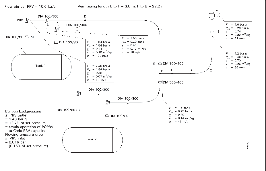
Figure 2 Two Phase Propane Properties at Code PRV Relief Flowrate - Simplified
Flow Sheet of a Cargo Tank Vent System With One Vent Stack Connected to Two
Tanks
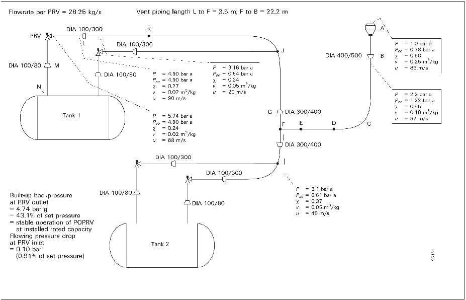
Figure 3 Two Phase Propane Properties at Installed Rated Flowrate - Simplified
Flow Sheet of a Cargo Tank Vent System With One Vent Stack Connected to Two
Tanks
Thus equations (2) and (3) predict a flow rate 17% higher
than RELDES
12.66 bar a, Vapour Fraction by mass at PRV inlet.
|
Vapour Mass per cubic metre
|
=
|
0.238 ×
26.9
|
=
|
6.402
kg
|
|
Liquid Mass per cubic metre
|
=
|
9.762 ×
475.0
|
=
|
361.95
kg
|
|
Total Mass per cubic metre
|
|
|
=
|
368.35
kg
|
|
and Vapour Fraction = 6.3/368 = 0.017
|
or Quality = 1.7% compared to RELDES 0.10%
At vent piping exit back pressure = 1.70 bar a
say at inlet to vent discharge pipe back pressure = 3.31
bar a:
By equation (5),
where 4f L/D = 4 × 0.005 × 3.04/0.203 = 0.30
Thus Back Pressure at PRV discharge flange:
-
= 1.70 + 1.59 = 3.29 bar a or = 2.29 bar
g (33.2 psig) for comparison with RELDES prediction
32.8 psig
-
= Thus equations (6),
(7), (8),
(9) and (5) predict a Back
Pressure 1% higher than RELDES