4.21
Type A independent tanks
4.21.1
Design basis
4.21.1.1 Type A independent tanks are tanks primarily
designed using classical ship-structural analysis procedures in accordance with
recognized standards. Where such tanks are primarily constructed of plane surfaces,
the design vapour pressure Po
shall be less than 0.07 MPa.
LR 4.21-01 Details of the proposed design are to be submitted for
consideration, and it is recommended that this be done at as early a stage as
possible.
4.21.1.2 If the cargo temperature at atmospheric
pressure is below -10°C, a complete secondary barrier shall be provided as required
in 4.5. The secondary barrier shall be designed in accordance with 4.6.
4.21.2
Structural analysis
4.21.2.1 A structural analysis shall be performed
taking into account the internal pressure as indicated in 4.13.2, and the
interaction loads with the supporting and keying system as well as a reasonable part
of the ship's hull.
4.21.2.2 For parts, such as supporting structures, not
otherwise covered by the requirements of the Code, stresses shall be determined by
direct calculations, taking into account the loads referred to in 4.12 to 4.15 as
far as applicable, and the ship deflection in way of supporting structures.
LR 4.21-02 Symbols:
|
b |
= |
width of plating supported, in metres |
|
f |
= |
1,1 -  but need not exceed 1,0 but need not exceed 1,0 |
|
fs |
= |
2,7 for nickel steels and carbon manganese steels |
| = |
3,9 for austenitic steels and aluminium alloys |
|
h |
= |
load head, in metres measured as follows
- for plating, the distance vertically from a point
one-third of the height of the plate above its lower edge to the top
of the tank
- for stiffeners, the distance from the middle of the
effective length to the top of the tank.
|
|
l |
= |
effective span or girder or web, in metres, see Pt 3, Ch
3,3.3 |
|
le |
= |
effective length of stiffening member, in metres, see Pt
3, Ch 3,3.3 |
lt, ls, lb,
lc are effective spans measured according to Fig. LR 4.1
|
ρ |
= |
maximum density of the cargo, in kg/m3, at the design
temperature |
|
k |
= |
higher tensile steel factor, see Pt 3, Ch 2,1.2 of the
Rules for Ships |
|
tp |
= |
thickness, in mm, of the attached load bearing plating. Where
this varies over the effective width of plating, the mean thickness is to be
used. |
|
P |
= |
harbour relief valve pressure, in MPa |
|
Peq |
= |
the internal pressure head, in MPa, as derived from 4.28.1.1 and
measured at a point on the plate one-third of the depth of the plate above
its lower edge |
|
s |
= |
spacing of bulkhead stiffeners, in mm |
|
S |
= |
spacing of primary members, in metres |
- Sw and s1 are as defined in Pt
3, Ch 10, Table 10.5.1 of the Rules for Ships
The lateral and torsional stability of stiffeners should comply with the
requirements of Pt 4, Ch 9,5.6 of the Rules for Ships.
LR 4.21-03 The scantlings of the cargo tanks are to comply with
the requirements of LR 4.21-04 and the following:
- Minimum thickness.
No part of the cargo tank structure
is to be less than 7,5 mm in thickness.
- Boundary plating.
The thickness of plating forming
the boundaries of cargo tanks is to be not less than 7,5 mm, nor less
than:
NOTE
Additional corrosion
allowance of 1 mm is to be added to the thickness derived if the cargo is of
corrosive nature, see also 4.3.5
where
- Rolled or built stiffeners.
The section modulus of
rolled or built stiffeners on plating forming tank boundaries is to be not
less than:
- Transverses.
The scantlings of transverse members are
normally to be derived using direct calculation methods. The structural
analysis is to take account of the internal pressure defined in 4.28.1.1 and
also those resulting from structural test loading conditions. Proper account
is also to be taken of structural model end constraints, shear and axial
forces present and any interaction from the double bottom structure through
the cargo tank supports. As an initial estimate the scantlings of the
primary transverses may be taken as:
Top transverse
Z = 720Peqslt2k
cm3
Topside transverse
Z = 520Peqslt2k
cm3
Side transverse
Z = 560Peqsls2k
cm3
Bottom transverse
Z = 560Peqslb2k
cm3
Centreline bulkhead transverse
Z = 400Peqslc2k
cm3
The depth of the bottom transverse web
is generally to be not less than 
Web stiffening is to be in
accordance with Pt 4, Ch 9,10.5 of the Rules for Ships with the application
of the stiffening requirements as shown in Fig. LR 4.1.
- Tank end webs and girders.
The section modulus of
vertical webs and horizontal girders is to be not less than:
Z = 850Peqbl2k
cm3
- Internal bulkheads (Perforated).
The thickness of
plating is to be not less than 7,5 mm, but may require to be increased at
the tank boundaries in regions of high local loading. The section modulus of
stiffeners, girders and webs is to be in accordance with Pt 4, Ch 9,8 and Ch
9,9.8 of the Rules for Ships.
- Internal bulkheads (Non-perforated).
- Where a bulkhead may be subjected to an internal pressure
head, Peq, resulting from loading on one side only,
the scantlings of plating, and stiffeners are to be determined from (b)
and (c), see also (j).
- Where no such loading condition is envisaged, and where the
arrangement of the centreline bulkhead in way of the tank dome creates a
common vapour space between the port and starboard sides of the tank,
the scantlings may be derived as follows:
The thickness of
plating and the section modulus of stiffeners are to be derived from
(b) and (c) respectively, but Peq (in MPa) need
not exceed the greater of:

- where
|
bt |
= |
maximum breadth from centreline bulkhead to tank
side |
|
ay |
= |
maximum dimensionless accelerations in
transverse direction, see 4.28.2. |
In such instances, due consideration is to be given
to the tank testing procedures and the Loading Manual is to include
the following note:
‘Centreline bulkhead
scantlings of cargo tanks are approved for symmetrical filling
levels either side of the centreline bulkhead in sea-going
conditions.’
- Tank crown structure.
Where the minimum thickness of
tank boundary plating (7,5 mm) has been adopted, the section modulus of
associated stiffeners and transverses are to be derived as above, but
Peq is to be not less than that equivalent to the
minimum thickness, that is:
The tank crown plating and stiffeners are
also to be suitable for a head equivalent to the greater of:
- the harbour relief valve pressure; or
- the tank test air pressure where the tank is to be
hydropneumatically tested.
- Connection of stiffeners to primary supporting members.
In assessing the arrangement at intersections of continuous
secondary and primary members, the requirements of Pt 3, Ch 10,5.2 are to be
complied with using the requirements for other ship types. The total load,
P, in kN, is to be derived using the internal pressure head,
Peq, in MPa as given in 4.28.1.1 and the following
formulae:
- In general:
P = 1000
(Sw - 0,5s1)
s1
Peq kN
- For wash bulkheads:
P = 1200
(Sw - 0,5s1)
s1
Peq kN
- Where the cargo tank boundary scantlings are based on the internal
pressure head, Zβ, measured with respect to the non-perforated
internal bulkhead such as centreline bulkhead, the valve(s) fitted in the
bulkhead should normally be kept closed and only be used for levelling
operations. This is to be indicated in the operational manual required in
18.2.1
4.21.2.3 The tanks with supports shall be designed for
the accidental loads specified in 4.15. These loads need not be combined with each
other or with environmental loads.
LR 4.21-04 In accordance with 4.21.2.3 tank boundaries and
transverse wash bulkheads, where fitted, should be able to withstand a collision
force acting on the tank supports corresponding to one half the weight of the tank
and cargo in the forward direction and one quarter the weight of the tank and cargo
in the aft direction without deformation likely to endanger the tank structure.
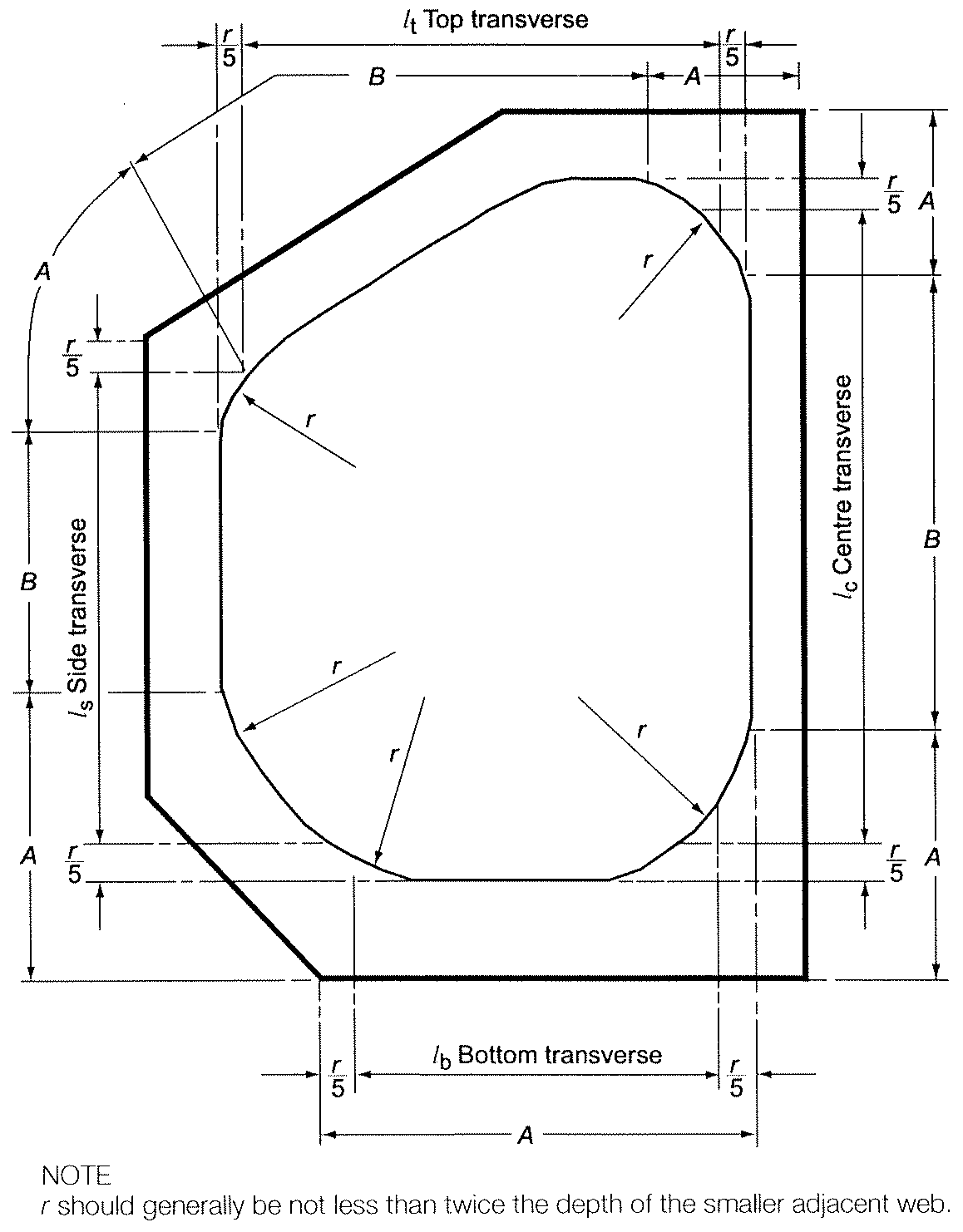
Fig. LR 4.1 Measurement of
spans
4.21.3
Ultimate design condition
4.21.3.1 For tanks primarily constructed of plane
surfaces, the nominal membrane stresses for primary and secondary members
(stiffeners, web frames, stringers, girders), when calculated by classical analysis
procedures, shall not exceed the lower of Rm
/2.66 or Re
/1.33 for nickel steels, carbon-manganese steels, austenitic steels and
aluminium alloys, where Rm
and Re
are defined in 4.18.1.3. However, if detailed calculations are carried out for
the primary members, the equivalent stress σc
, as defined in 4.18.1.4, may be increased over that indicated above to a stress
acceptable to the Administration or recognized organization acting on its behalf.
Calculations shall take into account the effects of bending, shear, axial and
torsional deformation as well as the hull/cargo tank interaction forces due to the
deflection of the double bottom and cargo tank bottoms.
4.21.3.2 Tank boundary scantlings shall meet at least
the requirements of the Administration or recognized organization acting on its
behalf for deep tanks taking into account the internal pressure as indicated in
4.13.2 and any corrosion allowance required by 4.3.5.
4.21.3.3 The cargo tank structure shall be reviewed
against potential buckling.
4.21.4
Accident design condition
4.21.4.1 The tanks and the tank supports shall be
designed for the accidental loads and design conditions specified in 4.3.4.3 and
4.15, as relevant.
4.21.4.2 When subjected to the accidental loads
specified in 4.15, the stress shall comply with the acceptance criteria specified in
4.21.3, modified as appropriate, taking into account their lower probability of
occurrence.
4.21.5
Testing
All type A independent tanks shall be subjected to a hydrostatic or
hydropneumatic test. This test shall be performed such that the stresses
approximate, as far as practicable, the design stresses, and that the pressure at
the top of the tank corresponds at least to the MARVS. When a hydropneumatic test is
performed, the conditions shall simulate, as far as practicable, the design loading
of the tank and of its support structure, including dynamic components, while
avoiding stress levels that could cause permanent deformation.
LR 4.21-05 If a hydropneumatic or a hydrostatic test is utilised,
the test head of water and air pressure are to be specified by designers. Details
and procedures of the hydropneumatic or hydrostatic test are to be submitted for
approval.
LR 4.21-06 The scantlings of the tanks are to comply with LR
4.21-03, using equivalent internal pressure for the test condition.
LR 4.21-07 The primary structures of the tanks are to comply with
Ch 2, 4.7 Tank test condition of the ShipRight Structural Design
Assessment Procedure for Type A Tank Liquefied Gas Carriers and Ch 2, 4.7
Tank test condition of the ShipRight Structural Design Assessment
Primary Hull and Cargo Tank Structure of Liquefied Gas Carriers Fitted with Type
B Independent Tanks Primarily Constructed of Plane Surfaces for type A tanks
and type B tanks primarily constructed of plane surfaces respectively.
4.22 Type B independent tanks
4.22.1
Design basis
4.22.1.1 Type B independent tanks are tanks designed
using model tests, refined analytical tools and analysis methods to determine stress
levels, fatigue life and crack propagation characteristics. Where such tanks are
primarily constructed of plane surfaces (prismatic tanks), the design vapour
pressure Po
shall be less than 0.07 MPa.
4.22.1.2 If the cargo temperature at atmospheric
pressure is below -10°C, a partial secondary barrier with a small leak protection
system shall be provided as required in 4.5. The small leak protection system shall
be designed according to 4.7.
4.22.2
Structural analysis
4.22.2.1 The effects of all dynamic and static loads
shall be used to determine the suitability of the structure with respect to:
- .1 plastic deformation;
- .2 buckling;
- .3 fatigue failure; and
- .4 crack propagation.
Finite element analysis or similar methods and fracture mechanics
analysis, or an equivalent approach, shall be carried out.
4.22.2.2 A three-dimensional analysis shall be carried
out to evaluate the stress levels, including interaction with the ship's hull. The
model for this analysis shall include the cargo tank with its supporting and keying
system, as well as a reasonable part of the hull.
4.22.2.3 A complete analysis of the particular ship
accelerations and motions in irregular waves, and of the response of the ship and
its cargo tanks to these forces and motions shall be performed, unless the data is
available from similar ships.
4.22.3
Ultimate design condition
4.22.3.1 Plastic deformation
4.22.3.1.1 For type B independent tanks, primarily
constructed of bodies of revolution, the allowable stresses shall not exceed:
-
|
σm
|
≤ f
|
|
σL
|
≤ 1.5f
|
|
σb
|
≤ 1.5F
|
|
σL
+σb
|
≤ 1.5F
|
|
σm
+σb
|
≤ 1.5F
|
|
σm
+σb
+σg
|
≤ 3.0F
|
|
σL
+σb
+σg
|
≤ 3.0F
|
where:
|
σm
|
= |
equivalent primary general membrane stress; |
|
σL
|
= |
equivalent primary local membrane stress; |
|
σb
|
= |
equivalent primary bending stress; |
|
σg
|
= |
equivalent secondary stress; |
|
f
|
= |
the lesser of (Rm
/ A) or (Re
/ B); and |
|
F
|
= |
the lesser of (Rm
/ C) or (Re
/ D), |
with Rm
and Re
as defined in 4.18.1.3. With regard to the stresses σm
, σL
, σb
and σg
, the definition of stress categories in 4.28.3 are referred. The values A and B
shall be shown on the International Certificate of Fitness for the Carriage of
Liquefied Gases in Bulk and shall have at least the following minimum values:
|
|
Nickel steels and carbon manganese steels
|
Austenitic steels
|
Aluminium alloys
|
| A
|
3
|
3.5
|
4
|
| B
|
2
|
1.6
|
1.5
|
| C
|
3
|
3
|
3
|
| D
|
1.5
|
1.5
|
1.5
|
The above figures may be altered, taking into account the design
condition considered in acceptance with the Administration.
LR 4.22-01 Type B independent tanks constructed of bodies of
revolution are to be designed to comply with the allowable stresses given in
4.22.3.1.1.
4.22.3.1.2 For type B independent tanks, primarily
constructed of plane surfaces, the allowable membrane equivalent stresses applied
for finite element analysis shall not exceed:
-
.1 for nickel steels and carbon-manganese
steels, the lesser of Rm
/2 or Re
/1.2;
-
.2 for austenitic steels, the lesser of
Rm
/2.5 or Re
/1.2; and
-
.3 for aluminium alloys, the lesser of
Rm
/2.5 or Re
/1.2.
The above figures may be amended, taking into account the locality of
the stress, stress analysis methods and design condition considered in acceptance
with the Administration.
LR 4.22-02 The stress levels to be complied with for type B
independent tanks primarily constructed of plane surfaces will be specially
considered, see also 4.22.3.1.2.
4.22.3.1.3 The thickness of the skin plate and the size
of the stiffener shall not be less than those required for type A independent
tanks.
LR 4.22-03 Type B independent tanks are to be subjected to a
structural analysis by direct calculation procedures at a high confidence level. It
is recommended that the assumptions made and the proposed calculation procedures be
agreed with LR at an early stage. Where necessary, model or other tests may be
required. Generally the scantlings of cargo tanks primarily constructed of plane
surfaces are not to be less than required by LR 4.21-03 and LR 4.21-04 for Type A
independent tanks.
4.22.3.2
Buckling
Buckling strength analyses of cargo tanks subject to external pressure
and other loads causing compressive stresses shall be carried out in accordance with
recognized standards. The method shall adequately account for the difference in
theoretical and actual buckling stress as a result of plate edge misalignment, lack
of straightness or flatness, ovality and deviation from true circular form over a
specified arc or chord length, as applicable.
4.22.4
Fatigue design condition
4.22.4.1 Fatigue and crack propagation assessment shall
be performed in accordance with 4.18.2. The acceptance criteria shall comply with
4.18.2.7, 4.18.2.8 or 4.18.2.9, depending on the detectability of the defect.
4.22.4.2 Fatigue analysis shall consider construction
tolerances.
4.22.4.3 Where deemed necessary by the Administration,
model tests may be required to determine stress concentration factors and fatigue
life of structural elements.
LR 4.22-04 Fatigue and crack propagation assessment shall be
performed in accordance with 4.18.2. The acceptance criteria shall comply with
4.18.2.7, 4.18.2.8 or 4.18.2.9, depending on the detectability of the defect. Due
consideration of quality control aspects such as misalignment, distortion, fit-up
and weld shape are also to be taken into account. In general, and in addition to the
Cw values dependent on detectability specified in 4.18.2.7, 4.18.2.8
and 4.18.2.9, a Cw value of 0,1 is to be used for all primary members.
Alternative proposals will be specially considered.
4.22.5
Accident design condition
4.22.5.1 The tanks and the tank supports shall be
designed for the accidental loads and design conditions specified in 4.3.4.3 and
4.15, as applicable.
4.22.5.2 When subjected to the accidental loads
specified in 4.15, the stress shall comply with the acceptance criteria specified in
4.22.3, modified as appropriate, taking into account their lower probability of
occurrence.
4.22.6
Testing
Type B independent tanks shall be subjected to a hydrostatic or
hydropneumatic test as follows:
-
.1 the test shall be performed as required in
4.21.5 for type A independent tanks; and
-
.2 in addition, the maximum primary membrane
stress or maximum bending stress in primary members under test conditions
shall not exceed 90% of the yield strength of the material (as fabricated)
at the test temperature. To ensure that this condition is satisfied, when
calculations indicate that this stress exceeds 75% of the yield strength,
the prototype test shall be monitored by the use of strain gauges or other
suitable equipment.
4.22.7
Marking
Any marking of the pressure vessel shall be achieved by a method that
does not cause unacceptable local stress raisers.
4.23
Type C independent tanks
4.23.1
Design basis
4.23.1.1 The design basis for type C independent tanks
is based on pressure vessel criteria modified to include fracture mechanics and
crack propagation criteria. The minimum design pressure defined in 4.23.1.2 is
intended to ensure that the dynamic stress is sufficiently low, so that an initial
surface flaw will not propagate more than half the thickness of the shell during the
lifetime of the tank.
4.23.1.2 The design vapour pressure shall not be less
than:
Po
= 0.2 + AC(ρr
)1.5 (MPa)
where:
|
A
|
= |

|
with:
|
σm
|
= |
design primary membrane stress; |
|
ΔσA
|
= |
allowable dynamic membrane stress (double amplitude at
probability level Q = 10-8) and equal to: |
- - 55 N/mm2 for ferritic-perlitic, martensitic and austenitic
steel;
- - 25 N/mm2 for aluminium alloy (5083-O);
|
C
|
= |
a characteristic tank dimension to be taken as the greatest of
the following: |
|
h
|
= |
height of tank (dimension in ship's vertical direction)
(m); |
|
b
|
= |
width of tank (dimension in ship's transverse
direction)(m); |
|
ℓ
|
= |
length of tank (dimension in ship's longitudinal direction)
(m); |
|
ρr
|
= |
the relative density of the cargo (ρr
= 1 for fresh water) at the design temperature. |
When a specified design life of the tank is longer than 108
wave encounters, ΔσA
shall be modified to give equivalent crack propagation corresponding to the
design life.
LR 4.23-01 If the carriage of products not covered by the Code is
intended, it is to be verified that the double amplitude of the primary membrane
stress, Δσm created by the maximum dynamic pressure differential ΔP does
not exceed the allowable double amplitude of the dynamic membrane stress,
ΔσA as specified in paragraph 4.23.1.2 of the Code:
Δσm ≤ ΔσA
The maximum dynamic pressure differential ΔP is to be calculated as
follows:
where
ρ is maximum liquid cargo density in kg/m3 at the design
temperature
αβ, Zβ are as defined in 4.28.1.2 of the Code, see
also Figure LR 4.5 Maximum dynamic pressure differential
αβ1, Zβ1 are the αβ and Zβ
values giving the maximum liquid pressure (Pgd)max
αβ2, Zβ2 are the αβ and Zβ
values giving the minimum liquid pressure (Pgd)min
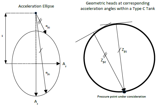
Figure LR 4.5 Maximum dynamic
pressure differential
LR 4.23-02 The requirement of LR 4.23-01 is to be applied unless
specified otherwise by the National Administration.
LR 4.23-03 Alternative means of calculating the design vapour
pressure referred to in 4.23.1.2 may be specially considered and are to be
acceptable to the National Administration.
4.23.1.3 The Administration may allocate a tank
complying with the criteria of type C tank minimum design pressure as in 4.23.1.2,
to a type A or type B, dependent on the configuration of the tank and the
arrangement of its supports and attachments.
LR 4.23-04 Before construction of the pressure vessels is
commenced, the following particulars, where applicable, and plans are to be
submitted for approval:
- Nature of cargoes, together with maximum vapour pressures and
minimum liquid temperature for which the pressure vessels are to be
approved, and proposed hydraulic test pressure.
- Particulars of materials proposed for the construction of the
vessels.
- Particulars of refrigeration equipment.
- General arrangement plan showing location of pressure vessels in
the ship.
- Plans of pressure vessels showing attachments, openings,
dimensions, details of welded joints and particulars of proposed stress
relief heat treatment.
- Plans of seatings, securing arrangements and deck sealing
arrangements.
- Plans showing arrangement of mountings, level gauges and number,
type and size of safety valves.
4.23.2
Shell thickness
4.23.2.1 The shell thickness shall be as follows:
-
.1 For pressure vessels, the thickness
calculated according to 4.23.2.4 shall be considered as a minimum thickness
after forming, without any negative tolerance.
-
.2 For pressure vessels, the minimum thickness
of shell and heads including corrosion allowance, after forming, shall not
be less than 5 mm for carbon-manganese steels and nickel steels, 3 mm for
austenitic steels or 7 mm for aluminium alloys.
-
.3 The welded joint efficiency factor to be
used in the calculation according to 4.23.2.4 shall be 0.95 when the
inspection and the non-destructive testing referred to in 6.5.6.5 are
carried out. This figure may be increased up to 1 when account is taken of
other considerations, such as the material used, type of joints, welding
procedure and type of loading. For process pressure vessels, the
Administration or recognized organization acting on its behalf may accept
partial non-destructive examinations, but not less than those of 6.5.6.5,
depending on such factors as the material used, the design temperature, the
nil-ductility transition temperature of the material, as fabricated, and the
type of joint and welding procedure, but in this case an efficiency factor
of not more than 0.85 shall be adopted. For special materials, the
above-mentioned factors shall be reduced, depending on the specified
mechanical properties of the welded joint.
4.23.2.2 The design liquid pressure defined in 4.13.2
shall be taken into account in the internal pressure calculations.
4.23.2.3 The design external pressure
Pe
, used for verifying the buckling of the pressure vessels, shall not be less
than that given by:
- Pe
= P1
+P2
+P3
+P4
(MPa),
- where:
|
P1
|
= |
setting value of vacuum relief valves. For vessels not fitted
with vacuum relief valves, P1 shall be specially considered, but
shall not, in general, be taken as less than 0.025 MPa; |
|
P2
|
= |
the set pressure of the pressure relief valves (PRVs) for
completely closed spaces containing pressure vessels or parts of pressure
vessels; elsewhere P2
=0; |
|
P3
|
= |
compressive actions in or on the shell due to the weight and
contraction of thermal insulation, weight of shell including corrosion
allowance and other miscellaneous external pressure loads to which the
pressure vessel may be subjected. These include, but are not limited to,
weight of domes, weight of towers and piping, effect of product in the
partially filled condition, accelerations and hull deflection. In addition,
the local effect of external or internal pressures or both shall be taken
into account; and |
|
P4
|
= |
external pressure due to head of water for pressure vessels or
part of pressure vessels on exposed decks; elsewhere P4
= 0. |
4.23.2.4 Scantlings based on internal pressure shall be
calculated as follows: the thickness and form of pressure-containing parts of
pressure vessels, under internal pressure, as defined in 4.13.2, including flanges,
shall be determined. These calculations shall in all cases be based on accepted
pressure vessel design theory. Openings in pressure-containing parts of pressure
vessels shall be reinforced in accordance with recognized standards.
LR 4.23-05 The thickness of pressure parts subject to internal
pressure is to be in accordance with Pt 5, Ch 11 of the Rules for Ships except
that:
- the welded joint efficiency factor, J, is to be as
defined in 4.23.2.1.3
- the allowable stress is to be in accordance with 4.23.3.1,
- the corrosion allowance (c) included in the formulae in Pt 5, Ch
11,2 of the Rules for Ships may require to be increased in accordance with
4.3.5.
4.23.2.5 Stress analysis in respect of static and
dynamic loads shall be performed as follows:
-
.1 Pressure vessel scantlings shall be
determined in accordance with 4.23.2.1 to 4.23.2.4 and 4.23.3.
-
.2 Calculations of the loads and stresses in
way of the supports and the shell attachment of the support shall be made.
Loads referred to in 4.12 to 4.15 shall be used, as applicable. Stresses in
way of the supporting structures shall be to a recognized standard
acceptable to the Administration or recognized organization acting on its
behalf. In special cases, a fatigue analysis may be required by the
Administration or recognized organization acting on its behalf.
-
.3 If required by the Administration or
recognized organization acting on its behalf, secondary stresses and thermal
stresses shall be specially considered.
LR 4.23-06 Where the inner hull directly supports the containment
system it is to comply with the requirements of LR 3.18-02.
4.23.3
Ultimate design condition
4.23.3.1 Plastic deformation
For type C independent tanks, the allowable stresses shall not
exceed:
-
|
σm
|
≤
f
|
|
σL
|
≤
1.5f
|
|
σb
|
≤
1.5f
|
|
σL
+σb
|
≤
1.5f
|
|
σm
+σb
|
≤
1.5f
|
|
σm
+σb
+σg
|
≤
3.0f
|
|
σL
+σb
+σg
|
≤
3.0f
|
where:
|
σm
|
= |
equivalent primary general membrane stress; |
|
σL
|
= |
equivalent primary local membrane stress; |
|
σb
|
= |
equivalent primary bending stress; |
|
σg
|
= |
equivalent secondary stress; and |
|
f
|
= |
the lesser of Rm
/ A or Re
/ B, |
with Rm
and Re
as defined in 4.18.1.3. With regard to the stresses σm
, σL
, σb
and σg
, the definition of stress categories in 4.28.3 are referred. The values A and B
shall be shown on the International Certificate of Fitness for the Carriage of
Liquefied Gases in Bulk and shall have at least the following minimum values:
|
|
Nickel steels and carbon- manganese steels
|
Austenitic steels
|
Aluminium alloys
|
| A
|
3
|
3.5
|
4
|
| B
|
1.5
|
1.5
|
1.5
|
LR 4.23-07 The circumferential stresses at supports of Type C
tanks, are to be calculated by a procedure acceptable to LR for an agreed number of
load cases.
LR 4.23-08 For stiffening rings of Type C tanks, the equivalent
stress is to be calculated over the full extent of the stiffening ring by a
procedure acceptable to LR, for an agreed number of load cases. For horizontal
cylindrical tanks made of C-Mn steel supported in saddles, the equivalent stress in
the stiffener rings is not to exceed the following values where calculated using
finite element analysis:
σe ≤ σall
where
|
σall |
= |
the lesser of 0,57Rm or 0,85Re |
|
σe |
= |
 |
|
σe |
= |
von Mises equivalent stress in N/mm2 |
|
σn |
= |
normal stress in N/mm2 in the circumferential
direction of the stiffening ring |
|
σb |
= |
bending stress in N/mm2 in the circumferential
direction of the stiffening ring |
|
τ |
= |
shear stress in N/mm2 in the stiffening ring |
Rm and Re as defined in 4.18.1.3 of the Code.
LR 4.23-09 The following assumptions are to be made for the
stiffening rings:
- The stiffening ring is to be considered as a circumferential beam
formed by web, face plate, doubler plate, if any, and associated shell
plating.
- For cylindrical shells the effective width of the associated
plating is to be taken as not greater than
 on each side of the web. A doubler plate, if
any, may be included within that distance.
on each side of the web. A doubler plate, if
any, may be included within that distance.
- where
|
r |
= |
mean radius of the cylindrical shell (mm) |
|
t |
= |
shell thickness (mm) |
- For longitudinal bulkheads (in the case of lobe tanks) the
effective width is to be specially considered. A value of 20tb on
each side of the web may be taken as a guidance value.
- where
|
tb |
= |
bulkhead thickness (mm). |
- The stiffening ring should be loaded with circumferential forces, on
each side of the ring, due to the shear stress, determined by the bi-dimensional
shear flow theory from the shear force of the tank.
LR 4.23-10 The buckling strength of the stiffening rings, of Type
C tanks is to be examined.
LR 4.23-11 For the calculation of reaction forces at the supports
of Type C tanks, the following factors are to be taken into account:
- Elasticity of support material (intermediate layer of wood or
similar material).
- Change in contact surface between tank and support, and of the
relevant reactions, due to thermal shrinkage of tank or elastic deformations of
tank and support material.
The final distribution of the reaction forces at the supports should not
show any tensile forces.
LR 4.23-12 The requirements of LR 4.23-07 to LR 4.23-11 are to be
applied unless specified otherwise by the National Administration.
4.23.3.2 Buckling criteria shall be as follows: the
thickness and form of pressure vessels subject to external pressure and other loads
causing compressive stresses shall be based on calculations using accepted pressure
vessel buckling theory and shall adequately account for the difference in
theoretical and actual buckling stress as a result of plate edge misalignment,
ovality and deviation from true circular form over a specified arc or chord
length.
4.23.4
Fatigue design condition
For large type C independent tanks, where the cargo at atmospheric
pressure is below -55°C, the Administration or recognized organization acting on its
behalf may require additional verification to check their compliance with 4.23.1.1
regarding static and dynamic stress.
4.23.5
Accident design condition
4.23.5.1 The tanks and the tank supporting structures
shall be designed for the accidental loads and design conditions specified in
4.3.4.3 and 4.15, as applicable.
4.23.5.2 When subjected to the accidental loads
specified in 4.15, the stress shall comply with the acceptance criteria specified in
4.23.3.1, modified as appropriate taking into account their lower probability of
occurrence.
4.23.6
Testing
4.23.6.1 Each pressure vessel shall be subjected to a
hydrostatic test at a pressure measured at the top of the tanks, of not less than
1.5 Po. In no case during the pressure test shall the calculated
primary membrane stress at any point exceed 90% of the yield stress of the material.
To ensure that this condition is satisfied where calculations indicate that this
stress will exceed 0.75 times the yield strength, the prototype test shall be
monitored by the use of strain gauges or other suitable equipment in pressure
vessels other than simple cylindrical and spherical pressure vessels.
4.23.6.2 The temperature of the water used for the test
shall be at least 30°C above the nil-ductility transition temperature of the
material, as fabricated.
4.23.6.3 The pressure shall be held for 2 h per 25 mm
of thickness, but in no case less than 2 h.
4.23.6.4 Where necessary for cargo pressure vessels, a
hydropneumatic test may be carried out under the conditions prescribed in 4.23.6.1
to 4.23.6.3.
LR 4.23-13 When a hydropneumatic test is performed, the
conditions are to simulate, so far as practicable, the actual loading of the tank
and its supports.
4.23.6.5 Special consideration may be given to the
testing of tanks in which higher allowable stresses are used, depending on service
temperature. However, the requirements of 4.23.6.1 shall be fully complied with.
4.23.6.6 After completion and assembly, each pressure
vessel and its related fittings shall be subjected to an adequate tightness test
which may be performed in combination with the pressure testing referred to in
4.23.6.1.
4.23.6.7 Pneumatic testing of pressure vessels other
than cargo tanks shall only be considered on an individual case basis. Such testing
shall only be permitted for those vessels designed or supported such that they
cannot be safely filled with water, or for those vessels that cannot be dried and
are to be used in a service where traces of the testing medium cannot be
tolerated.
4.23.7
Marking
The required marking of the pressure vessel shall be achieved by a
method that does not cause unacceptable local stress raisers.
4.24
Membrane tanks
4.24.1
Design basis
4.24.1.1 The design basis for membrane containment
systems is that thermal and other expansion or contraction is compensated for
without undue risk of losing the tightness of the membrane.
4.24.1.2 A systematic approach based on analysis and
testing shall be used to demonstrate that the system will provide its intended
function in consideration of the events identified in service as specified in
4.24.2.1.
4.24.1.3 If the cargo temperature at atmospheric
pressure is below -10°C, a complete secondary barrier shall be provided as required
in 4.5. The secondary barrier shall be designed according to 4.6.
4.24.1.4 The design vapour pressure Po
shall not normally exceed 0.025 MPa. If the hull scantlings are increased
accordingly and consideration is given, where appropriate, to the strength of the
supporting thermal insulation, Po
may be increased to a higher value, but less than 0.07 MPa.
4.24.1.5 The definition of membrane tanks does not
exclude designs such as those in which non-metallic membranes are used or where
membranes are included or incorporated into the thermal insulation.
4.24.1.6 The thickness of the membranes shall not
normally exceed 10 mm.
4.24.1.7 The circulation of inert gas throughout the
primary insulation space and the secondary insulation space, in accordance with
9.2.1, shall be sufficient to allow for effective means of gas detection.
4.24.2
Design considerations
4.24.2.1 Potential incidents that could lead to loss of
fluid tightness over the life of the membranes shall be evaluated. These include,
but are not limited to:
-
.1 Ultimate design events:
- .1 tensile failure of
membranes;
- .2 compressive collapse of
thermal insulation;
- .3 thermal ageing;
- .4 loss of attachment between
thermal insulation and hull structure;
- .5 loss of attachment of
membranes to thermal insulation system;
- .6 structural integrity of
internal structures and their supporting structures; and
- .7 failure of the supporting
hull structure.
-
.2 Fatigue design events:
- .1 fatigue of membranes
including joints and attachments to hull structure;
- .2 fatigue cracking of thermal
insulation;
- .3 fatigue of internal
structures and their supporting structures; and
- .4 fatigue cracking of inner
hull leading to ballast water ingress.
-
.3 Accident design events:
- .1 accidental mechanical damage
(such as dropped objects inside the tank while in service);
- .2 accidental
overpressurization of thermal insulation spaces;
- .3 accidental vacuum in the
tank; and
- .4 water ingress through the
inner hull structure.
Designs where a single internal event could cause simultaneous or
cascading failure of both membranes are unacceptable.
4.24.2.2 The necessary physical properties (mechanical,
thermal, chemical, etc.) of the materials used in the construction of the cargo
containment system shall be established during the design development in accordance
with 4.24.1.2.
4.24.3
Loads and load combinations
Particular consideration shall be given to the possible loss of tank
integrity due to either an overpressure in the interbarrier space, a possible vacuum
in the cargo tank, the sloshing effects, hull vibration effects, or any combination
of these events.
4.24.4
Structural analyses
4.24.4.1 Structural analyses and/or testing for the
purpose of determining the ultimate strength and fatigue assessments of the cargo
containment and associated structures, e.g. structures as defined in 4.9, shall be
performed. The structural analysis shall provide the data required to assess each
failure mode that has been identified as critical for the cargo containment
system.
4.24.4.2 Structural analyses of the hull shall take
into account the internal pressure as indicated in 4.13.2. Special attention shall
be paid to deflections of the hull and their compatibility with the membrane and
associated thermal insulation.
4.24.4.3 The analyses referred to in 4.24.4.1 and
4.24.4.2 shall be based on the particular motions, accelerations and response of
ships and cargo containment systems.
LR 4.24-01 The hull structure supporting the membrane tank is to
be incorporated into the ship structure finite element model, see LR III.5.
The scantlings of the inner hull are to be not less than required by LR 3.21-04,
see also LR 3.22-01.
4.24.5
Ultimate design condition
4.24.5.1 The structural resistance of every critical
component, subsystem or assembly shall be established, in accordance with 4.24.1.2,
for in-service conditions.
4.24.5.2 The choice of strength acceptance criteria for
the failure modes of the cargo containment system, its attachments to the hull
structure and internal tank structures, shall reflect the consequences associated
with the considered mode of failure.
4.24.5.3 The inner hull scantlings shall meet the
requirements for deep tanks, taking into account the internal pressure as indicated
in 4.13.2 and the specified appropriate requirements for sloshing load as defined in
4.14.3.
4.24.6
Fatigue design condition
4.24.6.1 Fatigue analysis shall be carried out for
structures inside the tank, i.e. pump towers, and for parts of membrane and pump
tower attachments, where failure development cannot be reliably detected by
continuous monitoring.
4.24.6.2 The fatigue calculations shall be carried out
in accordance with 4.18.2, with relevant requirements depending on:
4.24.6.3 For structural elements for which it can be
demonstrated by tests and/or analyses that a crack will not develop to cause
simultaneous or cascading failure of both membranes, Cw shall be less
than or equal to 0.5.
4.24.6.4 Structural elements subject to periodic
inspection, and where an unattended fatigue crack can develop to cause simultaneous
or cascading failure of both membranes, shall satisfy the fatigue and fracture
mechanics requirements stated in 4.18.2.8.
4.24.6.5 Structural element not accessible for
in-service inspection, and where a fatigue crack can develop without warning to
cause simultaneous or cascading failure of both membranes, shall satisfy the fatigue
and fracture mechanics requirements stated in 4.18.2.9.
LR 4.24-02 Containment system details, to be investigated by
fatigue analysis are to be submitted to LR for consideration, and it is recommended
that this be done at as early a stage as possible.
4.24.7
Accident design condition
4.24.7.1 The containment system and the supporting hull
structure shall be designed for the accidental loads specified in 4.15. These loads
need not be combined with each other or with environmental loads.
4.24.7.2 Additional relevant accident scenarios shall
be determined based on a risk analysis. Particular attention shall be paid to
securing devices inside tanks.
4.24.8
Design development testing
4.24.8.1 The design development testing required in
4.24.1.2 shall include a series of analytical and physical models of both the
primary and secondary barriers, including corners and joints, tested to verify that
they will withstand the expected combined strains due to static, dynamic and thermal
loads. This will culminate in the construction of a prototype-scaled model of the
complete cargo containment system. Testing conditions considered in the analytical
and physical models shall represent the most extreme service conditions the cargo
containment system will be likely to encounter over its life. Proposed acceptance
criteria for periodic testing of secondary barriers required in 4.6.2 may be based
on the results of testing carried out on the prototype-scaled model.
4.24.8.2 The fatigue performance of the membrane
materials and representative welded or bonded joints in the membranes shall be
determined by tests. The ultimate strength and fatigue performance of arrangements
for securing the thermal insulation system to the hull structure shall be determined
by analyses or tests.
4.24.9
Testing
4.24.9.1 In ships fitted with membrane cargo
containment systems, all tanks and other spaces that may normally contain liquid and
are adjacent to the hull structure supporting the membrane, shall be hydrostatically
tested.
4.24.9.2 All hold structures supporting the membrane
shall be tested for tightness before installation of the cargo containment
system.
4.24.9.3 Pipe tunnels and other compartments that do
not normally contain liquid need not be hydrostatically tested.
4.25
Integral tanks
4.25.1
Design basis
Integral tanks that form a structural part of the hull and are affected
by the loads that stress the adjacent hull structure shall comply with the
following:
-
.1 the design vapour pressure Po
as defined in 4.1.2 shall not normally exceed 0.025 MPa. If the hull
scantlings are increased accordingly, Po
may be increased to a higher value, but less than 0.07 MPa;
-
.2 integral tanks may be used for products,
provided the boiling point of the cargo is not below -10°C. A lower
temperature may be accepted by the Administration or recognized organization
acting on its behalf subject to special consideration, but in such cases a
complete secondary barrier shall be provided; and
-
.3 products required by chapter 19 to be
carried in type 1G ships shall not be carried in integral tanks.
4.25.2
Structural analysis
The structural analysis of integral tanks shall be in accordance with
recognized standards.
LR 4.25-01 Integral tanks are to be designed and constructed in
accordance with the requirements of the Rules for Ships. The scantlings of the tank
boundary plating and stiffening are to be not less than required as a deep tank by
Pt 4, Ch 1,9.2 of the Rules for Ships, using the heads given in that Section, or as
derived from 4.13.2.4, whichever is the greater, see also 4.25.1.1.
LR 4.25-02 Where direct calculation procedures are adopted in the
analysis of the hull structure, the assumptions made and other details of the
calculations are to be submitted.
4.25.3
Ultimate design condition
4.25.3.1 The tank boundary scantlings shall meet the
requirements for deep tanks, taking into account the internal pressure as indicated
in 4.13.2.
4.25.3.2 For integral tanks, allowable stresses shall
normally be those given for hull structure in the requirements of the Administration
or recognized organization acting on its behalf.
4.25.4
Accident design condition
4.25.4.1 The tanks and the tank supports shall be
designed for the accidental loads specified in 4.3.4.3 and 4.15, as relevant.
4.25.4.2 When subjected to the accidental loads
specified in 4.15, the stress shall comply with the acceptance criteria specified in
4.25.3, modified as appropriate, taking into account their lower probability of
occurrence.
4.25.5
Testing
All integral tanks shall be hydrostatically or hydropneumatically
tested. The test shall be performed so that the stresses approximate, as far as
practicable, to the design stresses and that the pressure at the top of the tank
corresponds at least to the MARVS.
4.26
Semi-membrane tanks
4.26.1 Design basis
4.26.1.1 Semi-membrane tanks are non-self-supporting
tanks when in the loaded condition and consist of a layer, parts of which are
supported through thermal insulation by the adjacent hull structure, whereas the
rounded parts of this layer connecting the above-mentioned supported parts are
designed also to accommodate the thermal and other expansion or contraction.
4.26.1.2 The design vapour pressure Po
shall not normally exceed 0.025 MPa. If the hull scantlings are increased
accordingly, and consideration is given, where appropriate, to the strength of the
supporting thermal insulation, Po
may be increased to a higher value, but less than 0.07 MPa.
4.26.1.3 For semi-membrane tanks the relevant
requirements in this section for independent tanks or for membrane tanks shall be
applied as appropriate.
4.26.1.4 In the case of semi-membrane tanks that comply
in all respects with the requirements applicable to type B independent tanks, except
for the manner of support, the Administration may, after special consideration,
accept a partial secondary barrier.