
2 Load model
2.1 General
The loads to be considered as acting on the bulkhead are
those given by the combination of the cargo loads with those induced
by the flooding of the foremost cargo hold.
The most severe combinations of cargo-induced loads and flooding
loads are to be used for the check of the scantlings of the bulkhead,
depending on the loading conditions included in the loading manual:
- homogeneous loading conditions;
- non-homogeneous loading conditions.
Non-homogeneous part loading conditions associated with multiport
loading and unloading operations for homogeneous loading conditions
need not to be considered according to these standards.
2.2 Bulkhead corrugation flooding head
The flooding head h
f (see figure 1) is the distance,
in m, measured vertically with the ship in the upright position, from
the calculation point to a level located at a distance d
f, in m, from the baseline equal to:
-
(a) in general:
-
(b) for ships less than 50,000 tonnes deadweight
with Type B freeboard:
|
D |
= |
the distance,
in m, from the baseline to the freeboard deck at side amidship (see figure 1).
|
-
(c) for ships to be operated at an assigned load
line draught T
r, less than the permissible
loadline draught T, the flooding head defined in (a)
and (b) may be reduced by T-T
r.
Figure 1
2.3 Pressure in the flooded hold
2.3.1 Bulk cargo loaded hold
Two cases are to be considered, depending on the values
of d
1 and d
f, d
1 (see figure 1)
being a distance from the baseline given, in m, by:
where:
|
M
c
|
= |
mass of cargo, in tonnes, in the foremost cargo hold |
|
ρ
c
|
= |
bulk cargo density, in t/m3
|
|
l
c
|
= |
length of the foremost cargo hold, in m |
|
B
|
= |
ship's
breadth amidships, in m |
|
V
LS
|
= |
volume, in m3, of the bottom stool above the inner
bottom
|
|
h
HT
|
= |
height of the hopper tanks amidship, in m, from the baseline |
|
h
DB
|
= |
height of the double bottom, in m |
|
b
HT
|
= |
breadth of the hopper tanks amidship, in m. |
-
(a)
d
f ≥ d
1
At each point of the bulkhead located at a distance between d
1 and d
f from the baseline,
the pressure p
c,f, in kN/m2, is
given by:
- where
|
ρ
|
= |
seawater
density, in t/m3
|
|
g
|
= |
9.81
m/s2, gravity acceleration
|
|
h
f
|
= |
flooding head as defined in section 2.2. |
At each point of the bulkhead located at a distance lower than d
1 and d
f from the baseline,
the pressure p
c,f, in kN/m2, is
given by:
- where
|
ρ, g, h
f
|
= |
as given above |
|
ρ
c
|
= |
bulk cargo density, in t/m3
|
|
perm
|
= |
permeability
of cargo, to be taken as 0.3 for ore (corresponding bulk cargo density
for iron ore may generally be taken as 3.0 t/m3).
|
|
h
1
|
= |
vertical distance, in m, from the calculation point to a level
located at a distance d
1, as defined above,
from the baseline (see figure
1)
|
|
γ |
= |
45°
– (ϕ/2) |
|
ϕ |
= |
angle of
repose of the cargo, in degrees, and may generally be taken as 35°
for iron ore. |
The force Fc,f, in kN, acting on a corrugation is
given by:
- where
|
s
1
|
= |
spacing of corrugations, in m (see figure 2a)
|
|
ρ, g, d
1
, h
DB
|
= |
as given above |
|
d
f
|
= |
as given in 2.2 |
|
(p
c,f)lc
|
= |
pressure, in kN/m2, at the lower
end of the corrugation
|
|
h
LS
|
= |
height of the lower stool, in m, from the inner bottom. |
-
(b)
d
f < d
1
At each point of the bulkhead located at a distance between d
f and d
1 from the baseline,
the pressure p
c,f, in kN/m2, is
given by:
- where:
|
ρ
c, g, h
1, γ
|
= |
as given in (a). |
At each point of the bulkhead located at a distance lower than d
f from the baseline, the pressure p
c,f, in kN/m2, is given by:
- where:
|
ρ, g, h
f, ρ
c, h
1, γ
|
= |
as given in (a). |
The force F
c,f in kN, acting on a corrugation
is given by:
- where:
|
s
1, ρ
c, g, γ, (p
c,f)lc, h
LS
|
= |
as given in
(a) |
|
d
1, h
DB
|
= |
as given above |
|
d
f
|
= |
as given in 2.2. |
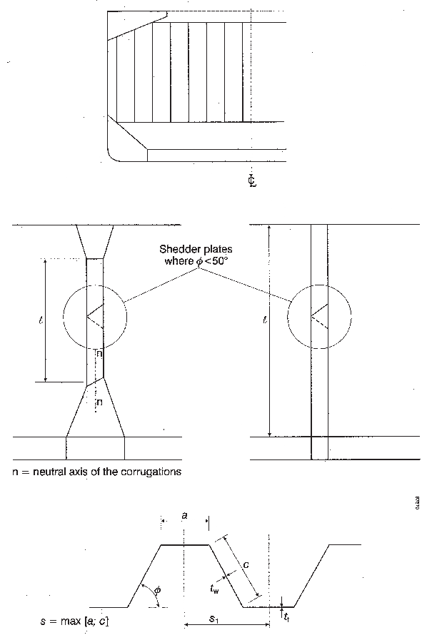
Figure 2a
Figure 2b
2.3.2 Empty hold
At each point of the bulkhead, the hydrostatic pressure p
f induced by the flooding head h
f is
to be considered.
The force F
f, in kN, acting on a corrugation
is given by:
where:
|
s
1, ρ, g, H
LS
|
= |
as
given in 2.3.1 (a) |
|
h
DB
|
= |
as given in 2.3.1 |
|
d
f
|
= |
as given in 2.2. |
2.4 Pressure in the non-flooded bulk cargo loaded
hold
At each point of the bulkhead, the pressure p
c, in kN/m2, is given by:
where:
|
ρ
c, g, h
1, γ
|
= |
as given in 2.3.1 (a). |
The force F
c, in kN, acting on a corrugation
is given by:
where:
|
ρ
c, g, s
1, h
LS, γ
|
= |
as given in 2.3.1 (a) |
|
d
1, h
DB
|
= |
as given in 2.3.1. |
2.5 Resultant pressure
2.5.1 Homogeneous loading conditions
At each point in the bulkhead structure, the resultant pressure p, in kN/m2, to be considered for the scantlings
of the bulkhead is given by:
The resultant force F, in kN, acting
on a corrugation is given by:
2.5.2 Non-homogeneous loading conditions
At each point in the bulkhead structure, the resultant pressure p, in kN/m2, to be considered for the scantlings
of the bulkhead is given by:
The resultant force F, in kN, acting
on a corrugation is given by:
In case the foremost cargo hold, in non-homogenous
loading conditions, is not allowed to be loaded, the resultant pressure p, in kN/m2, to be considered for the scantlings
of the bulkhead is given by:
and the resultant force F, in kN, acting
on a corrugation is given by:
|