1 SOLAS Regulation II-2/59.4 requires oil tankers constructed on or after 1 October 1994,
to be provided with suitable arrangements for gas freeing and ventilation
of double hull spaces. In addition, oil tankers fitted with inert
gas systems are required to have suitable arrangements for inerting
double hull spaces, when necessary.
2 The recommendations contained in this annex
are intended to provide an advice for alternative solutions available
and indicate acceptable arrangements.
Gas Freeing and Ventilation
3 The gas freeing and ventilation arrangements
must be capable of gasfreeing:
in order to maintain adequate ventilation continuously during
entry of personnel.
Alternative Methods of Ventilation
4 The following methods of ventilation are feasible:
-
.1 filling and subsequent emptying with water
ballast,
-
.2 using portable gas-freeing fan fitted to tank
openings with hose or pipe led to bottom of the tank. Discharge may
be through hatch or manhole (See
Fig. 1, 2 and 3). Pipes made of non-metallic material
may be accepted if documented to be of electrically conductive type
and suitably grounded. For acceptable results in larger L-shaped tanks,
the purge pipes should be led inboard to the centreline double bottom
girder. An alternative to portable fans is to use inert gas fans;
-
.3 same arrangement as paragraph 4.1.2, however,
extraction from bottom through purge pipe and fresh air supply from
deck (see
Fig.2.);
-
.4 connection between the inert gas line and the
water ballast line for fresh air supply through ballast suctions (see
Fig.3);
-
.5 cross-over ventilation (see
Fig.4);
-
.6 an arrangement utilizing dilution method with
inlet and outlet at deck level (see
figure 5). This method will require
a powerful fan so that the jet will penetrate all the way down to
the tank bottom. The high inlet velocity causes turbulent mixing with
the tank atmosphere. The gas being exhausted from the tank is at any
time a mixture of the gas supplied and the tank atmosphere. For L-shaped
tanks this method alone is normally not considered sufficient, but
in combination with air supply through ballast suctions, it may be
acceptable; and
-
.7 combination of partly filling and ventilation,
e.g. filling of double bottom section of U-shaped tanks and ventilation
of side spaces.
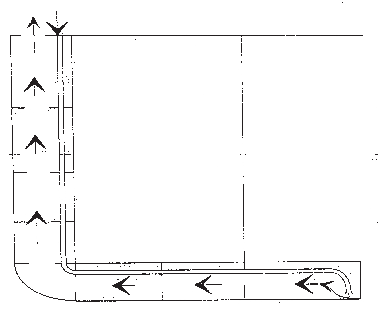
Figure 1 Ventilation by means of portable fan/inert gas fan and purge pipe
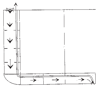
Figure 2 Gas freeing by means of portable fan and purge pipe
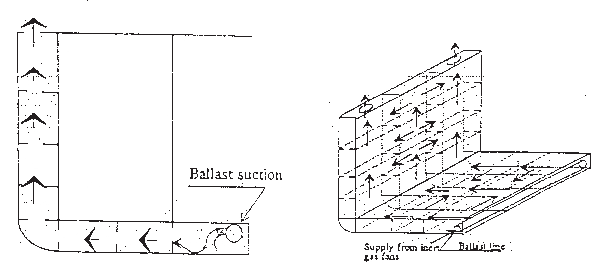
Figure 3 Ventilation with supply from inert gas fan through ballast
suction
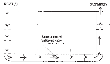
Figure 4 Cross-over ventilation through remote operated bulkhead valve(s)
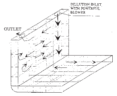
Figure 5 Ventilation by dilution method
5 Methods listed in paragraphs 4.1 to 4.5 are
based on displacement of gas, which is considered to be the best solution
for deep tanks of cellular design.
6 Most hydrocarbon gases from crude oil, hydrogen
sulphide and inert gas are heavier than air. With requirements for
connections for inert gas supply to ballast tanks, inerting of ballast
tanks will probably be a normal procedure. A ventilation arrangement
extracting the heavier gases from bottom utilizing portable fans mounted
on purge pipes and with fresh air supply from open hatches in deck
will probably be an effective gas-freeing method.
7 However, filling of ballast tanks and subsequent
emptying is considered as the most efficient way of gas-freeing ballast
tanks. Hull strength limitations must be observed.
8 The arrangements for inerting of double hull
spaces may be through portable connections to the inert gas system
for cargo tanks or by fixed piping connections.
9 If fixed piping is used, the arrangement must
include a separate deck water seal and a non-return valve in order
to prevent communication between vapour spaces of cargo tanks and
the double hull spaces. The practices for inerting double hull spaces
may either be to keep these spaces inerted at all times when empty,
or to inert them only if hydrocarbon gases are detected indicating
leakage between cargo tank(s) and the double hull spaces. If the former
practice is utilized, a fixed piping system is considered necessary.
Methods and Arrangements for Inerting
10 As for gas freeing and ventilation the easiest
method for inerting is to supply inert gas to the space during deballasting.
For that purpose an inert gas inlet in the top of the space is needed.
However, arrangements must additionally, be provided to enable the
space to be purged with inert gas. For this purpose at least L-shaped
tanks must be provided with inert gas supply outlets near bottom far
ends. Alternative arrangements for inert gas purging will be the same
as for ventilation purposes detailed in paragraphs 4,5,6 and 7, replacing
portable fan with inert gas supply inlets.
11 Written procedures should be available onboard
giving details on how to carry out ventilation, inerting of cleaning
or double hull spaces.