
Ship arrangements
Goal
To ensure that the cargo containment and handling system are located such that
the consequences of any release of cargo will be minimized, and to provide safe
access for operation and inspection.
3.1
Segregation of the cargo area
3.1.1 Hold spaces shall be segregated from machinery
and boiler spaces, accommodation spaces, service spaces, control stations, chain
lockers, domestic water tanks and from stores. Hold spaces shall be located forward
of machinery spaces of category A. Alternative arrangements, including locating
machinery spaces of category A forward, may be accepted, based on SOLAS regulation
II-2/17, after further consideration of involved risks, including that of cargo
release and the means of mitigation.
3.1.2 Where cargo is carried in a cargo containment
system not requiring a complete or partial secondary barrier, segregation of hold
spaces from spaces referred to in 3.1.1 or spaces either below or outboard of the
hold spaces may be effected by cofferdams, oil fuel tanks or a single gastight
bulkhead of all-welded construction forming an "A-60" class division. A gastight
"A-0" class division is acceptable if there is no source of ignition or fire hazard
in the adjoining spaces.
3.1.3 Where cargo is carried in a cargo containment
system requiring a complete or partial secondary barrier, segregation of hold spaces
from spaces referred to in 3.1.1, or spaces either below or outboard of the hold
spaces that contain a source of ignition or fire hazard, shall be effected by
cofferdams or oil fuel tanks. A gastight "A-0" class division is acceptable if there
is no source of ignition or fire hazard in the adjoining spaces.
LR 3.1-01 Cargo tank holds are to be separated from each other by
single bulkheads of all welded construction. Where, however, the design temperature
as defined in 4.1.3 is below –55°C, cofferdams are to be adopted unless the cargo is
carried in independent tanks and alternative arrangements are made to ensure the
bulkhead cannot be cooled to below –55°C. Cofferdams may be used as ballast tanks
subject to approval by LR.
3.1.4 Turret compartments segregation from spaces
referred to in 3.1.1, or spaces either below or outboard of the turret compartment
that contain a source of ignition or fire hazard, shall be effected by cofferdams or
an A-60 class division. A gastight "A-0" class division is acceptable if there is no
source of ignition or fire hazard in the adjoining spaces.
3.1.5 In addition, the risk of fire propagation from
turret compartments to adjacent spaces shall be evaluated by a risk analysis (see
1.1.11) and further preventive measures, such as the arrangement of a cofferdam
around the turret compartment, shall be provided if needed.
3.1.6 When cargo is carried in a cargo containment
system requiring a complete or partial secondary barrier:
-
.1 at temperatures below -10°C, hold spaces
shall be segregated from the sea by a double bottom; and
-
.2 at temperatures below -55°C, the ship shall
also have a longitudinal bulkhead forming side tanks.
LR 3.1-02 The double bottom requirements of Pt 4, Ch 1,8 are to be
applied regardless of the cargo temperature, see also LR 3.18.
3.1.7 Arrangements shall be made for sealing the
weather decks in way of openings for cargo containment systems.
3.2
Accommodation, service and machinery spaces and control stations
3.2.1 No accommodation space, service space or control
station shall be located within the cargo area. The bulkhead of accommodation
spaces, service spaces or control stations that face the cargo area shall be so
located as to avoid the entry of gas from the hold space to such spaces through a
single failure of a deck or bulkhead on a ship having a containment system requiring
a secondary barrier.
LR 3.2-01 Cargo service spaces as defined in 1.2.13 may be
situated within the cargo area, provided all other relevant requirements of these
Rules and the Rules for Ships are complied with.
3.2.2 To guard against the danger of hazardous vapours,
due consideration shall be given to the location of air intakes/outlets and openings
into accommodation, service and machinery spaces and control stations in relation to
cargo piping, cargo vent systems and machinery space exhausts from gas burning
arrangements.
3.2.3 Access through doors, gastight or otherwise,
shall not be permitted from a non-hazardous area to a hazardous area except for
access to service spaces forward of the cargo area through airlocks, as permitted by
3.6.1, when accommodation spaces are aft.
3.2.4.1 Entrances, air inlets and openings to
accommodation spaces, service spaces, machinery spaces and control stations shall
not face the cargo area. They shall be located on the end bulkhead not facing the
cargo area or on the outboard side of the superstructure or deckhouse or on both at
a distance of at least 4% of the length (L) of the ship but not less than 3 m
from the end of the superstructure or deckhouse facing the cargo area. This
distance, however, need not exceed 5 m.
3.2.4.2 Windows and sidescuttles facing the cargo area
and on the sides of the superstructures or deckhouses within the distance mentioned
above shall be of the fixed (non-opening) type. Wheelhouse windows may be non-fixed
and wheelhouse doors may be located within the above limits so long as they are
designed in a manner that a rapid and efficient gas and vapour tightening of the
wheelhouse can be ensured.
3.2.4.3 For ships dedicated to the carriage of cargoes
that have neither flammable nor toxic hazards, the Administration may approve
relaxations from the above requirements.
3.2.4.4 Accesses to forecastle spaces containing
sources of ignition may be permitted through a single door facing the cargo area,
provided the doors are located outside hazardous areas as defined in chapter 10.
3.2.5 Windows and sidescuttles facing the cargo area
and on the sides of the superstructures and deckhouses within the limits specified
in 3.2.4, except wheelhouse windows, shall be constructed to "A-60" class.
Sidescuttles in the shell below the uppermost continuous deck and in the first tier
of the superstructure or deckhouse shall be of fixed (non-opening) type.
3.2.6 All air intakes, outlets and other openings into
the accommodation spaces, service spaces and control stations shall be fitted with
closing devices. When carrying toxic products, they shall be capable of being
operated from inside the space. The requirement for fitting air intakes and openings
with closing devices operated from inside the space for toxic products need not
apply to spaces not normally manned, such as deck stores, forecastle stores,
workshops. In addition, the requirement does not apply to cargo control rooms
located within the cargo area.
LR 3.2-02 The closing devices detailed in 3.2.6 of the Code need
not be operable from within the single spaces listed but may be located in
centralised positions. The requirement for closing devices need not apply to the
following spaces:
LR 3.2-03 The closing devices detailed in 3.2.6 of the Code are
to give a reasonable degree of gas tightness. Ordinary steel fire-flaps without
gaskets/seals are not considered to be satisfactory.
LR 3.2-04 In addition to the requirements of LR 3.2-02 to LR
3.2-03, the closing devices are to be operable from outside of the protected space
in accordance with SOLAS regulation II-2/5.2.1.1.
3.2.7 Control rooms and machinery spaces of turret
systems may be located in the cargo area forward or aft of cargo tanks in ships with
such installations. Access to such spaces containing sources of ignition may be
permitted through doors facing the cargo area, provided the doors are located
outside hazardous areas or access is through airlocks.
3.3 Cargo machinery spaces and turret
compartments
3.3.1 Cargo machinery spaces shall be situated above
the weather deck and located within the cargo area. Cargo machinery spaces and
turret compartments shall be treated as cargo pump-rooms for the purpose of fire
protection according to SOLAS regulation II-2/9.2.4, and for the purpose of prevention of potential
explosion according to SOLAS regulation ll-2/4.5.10.
LR 3.3-01 The requirement of 3.3.1 is to be applied as
follows:
Cargo machinery spaces shall be situated above the weather deck and
located within the cargo area. Cargo machinery spaces and turret compartments shall
be treated as cargo pump-rooms for the purpose of fire protection according to SOLAS
regulation II-2/9.2.4. See also 11.1.1.1.
3.3.2 When cargo machinery spaces are located at the
after end of the aftermost hold space or at the forward end of the foremost hold
space, the limits of the cargo area, as defined in 1.2.7, shall be extended to
include the cargo machinery spaces for the full breadth and depth of the ship and
the deck areas above those spaces.
3.3.3 Where the limits of the cargo area are extended
by 3.3.2, the bulkhead that separates the cargo machinery spaces from accommodation
and service spaces, control stations and machinery spaces of category A shall be
located so as to avoid the entry of gas to these spaces through a single failure of
a deck or bulkhead.
3.3.4 Cargo compressors and cargo pumps may be driven
by electric motors in an adjacent non-hazardous space separated by a bulkhead or
deck, if the seal around the bulkhead penetration ensures effective gastight
segregation of the two spaces. Alternatively, such equipment may be driven by
certified safe electric motors adjacent to them if the electrical installation
complies with the requirements of chapter 10.
3.3.5 Arrangements of cargo machinery spaces and turret
compartments shall ensure safe unrestricted access for personnel wearing protective
clothing and breathing apparatus, and in the event of injury to allow unconscious
personnel to be removed. At least two widely separated escape routes and doors shall
be provided in cargo machinery spaces, except that a single escape route may be
accepted where the maximum travel distance to the door is 5 m or less.
3.3.6 All valves necessary for cargo handling shall be
readily accessible to personnel wearing protective clothing. Suitable arrangements
shall be made to deal with drainage of pump and compressor rooms.
3.3.7 Turret compartments shall be designed to retain
their structural integrity in case of explosion or uncontrolled high-pressure gas
release (overpressure and/or brittle fracture), the characteristics of which shall
be substantiated on the basis of a risk analysis with due consideration of the
capabilities of the pressure relieving devices.
3.4 Cargo control rooms
3.4.1 Any cargo control room shall be above the weather
deck and may be located in the cargo area. The cargo control room may be located
within the accommodation spaces, service spaces or control stations, provided the
following conditions are complied with:
-
.1 the cargo control room is a non-hazardous
area;
-
.2 if the entrance complies with 3.2.4.1, the
control room may have access to the spaces described above; and
-
.3 if the entrance does not comply with
3.2.4.1, the cargo control room shall have no access to the spaces described
above and the boundaries for such spaces shall be insulated to "A-60"
class.
3.4.2 If the cargo control room is designed to be a
non-hazardous area, instrumentation shall, as far as possible, be by indirect
reading systems and shall, in any case, be designed to prevent any escape of gas
into the atmosphere of that space. Location of the gas detection system within the
cargo control room will not cause the room to be classified as a hazardous area, if
installed in accordance with 13.6.11.
3.4.3 If the cargo control room for ships carrying
flammable cargoes is classified as a hazardous area, sources of ignition shall be
excluded and any electrical equipment shall be installed in accordance with chapter
10.
3.5
Access to spaces in the cargo area
3.5.1 Visual inspection of at least one side of the
inner hull structure shall be possible without the removal of any fixed structure or
fitting. If such a visual inspection, whether combined with those inspections
required in 3.5.2, 4.6.2.4 or 4.20.3.7 or not, is only possible at the outer face of
the inner hull, the inner hull shall not be a fuel-oil tank boundary wall.
3.5.2 Inspection of one side of any insulation in hold
spaces shall be possible. If the integrity of the insulation system can be verified
by inspection of the outside of the hold space boundary when tanks are at service
temperature, inspection of one side of the insulation in the hold space need not be
required.
3.5.3 Arrangements for hold spaces, void spaces, cargo
tanks and other spaces classified as hazardous areas, shall be such as to allow
entry and inspection of any such space by personnel wearing protective clothing and
breathing apparatus and shall also allow for the evacuation of injured and/or
unconscious personnel. Such arrangements shall comply with the following:
LR 3.5-01 The minimum clear opening detailed in 3.5.3.1.2 of
Code, of 600 mm x 600 mm may have corner radii up to 100 mm maximum. If, as a
consequence of structural analysis of a given design, the stress is to be reduced
around the opening, it is considered appropriate to take measures to reduce the
stress by making the opening larger with increased radii, e.g. 600 x 800 with 300 mm
radii, within which a clear opening of 600 mm x 600 mm with corner radii up to 100
mm maximum can fit.
LR 3.5-02 The minimum clear opening detailed in 3.5.3.1.3 of Code,
of not less than 600 mm x 800 mm may have corner radii up to 300 mm, see Figure
LR 3.7 Vertical Openings. An opening of 600 mm in height x 800 mm in width
may be accepted as access openings in vertical structures where it is not desirable
to make large vertical openings in structural members such as girders and floors in
double bottom tanks.
LR 3.5-03 Subject to verification of easy evacuation of an
injured person on a stretcher a vertical opening with maximum dimensions of 850 mm x
620 mm is considered an acceptable alternative, where the upper half is wider than
600 mm, and where the lower half is less than 600 mm, see Figure LR 3.8
Alternative Vertical Openings.
LR 3.5-04 If the bottom of a vertical opening is at a height of
more than 600 mm above the deck, steps and handgrips are to be provided. In such
arrangements it is to be demonstrated that an injured person can be easily
evacuated.
-
-
.2 The dimensions referred to in 3.5.3.1.2 and
3.5.3.1.3 may be decreased, if the requirements of 3.5.3 can be met to the
satisfaction of the Administration.
-
.3 Where cargo is carried in a containment
system requiring a secondary barrier, the requirements of 3.5.3.1.2 and
3.5.3.1.3 do not apply to spaces separated from a hold space by a single
gastight steel boundary. Such spaces shall be provided only with direct or
indirect access from the weather deck, not including any enclosed
non-hazardous area.
-
.4 Access required for inspection shall be a
designated access through structures below and above cargo tanks, which
shall have at least the cross-sections as required by 3.5.3.1.3.
-
.5 For the purpose of 3.5.1 or 3.5.2, the
following shall apply:
-
.1 where it is required to pass between
the surface to be inspected, flat or curved, and structures such as
deck beams, stiffeners, frames, girders, etc., the distance between
that surface and the free edge of the structural elements shall be
at least 380 mm. The distance between the surface to be inspected
and the surface to which the above structural elements are fitted,
e.g. deck, bulkhead or shell, shall be at least 450 mm for a curved
tank surface (e.g. for a type C tank), or 600 mm for a flat tank
surface (e.g. for a type A tank) (see figure 3.1);
-
.2 where it is not required to pass
between the surface to be inspected and any part of the structure,
for visibility reasons the distance between the free edge of that
structural element and the surface to be inspected shall be at least
50 mm or half the breadth of the structure's face plate, whichever
is the larger (see figure 3.2);
-
.3 if for inspection of a curved
surface where it is required to pass between that surface and
another surface, flat or curved, to which no structural elements are
fitted, the distance between both surfaces shall be at least 380 mm
(see figure 3.3). Where it is not required to pass between that
curved surface and another surface, a smaller distance than 380 mm
may be accepted taking into account the shape of the curved
surface;
-
.4 if for inspection of an
approximately flat surface where it is required to pass between two
approximately flat and approximately parallel surfaces, to which no
structural elements are fitted, the distance between those surfaces
shall be at least 600 mm. Where fixed access ladders are fitted, a
clearance of at least 450 mm shall be provided for access (see
figure 3.4);
-
.5 the minimum distances between a
cargo tank sump and adjacent double bottom structure in way of a
suction well shall not be less than those shown in figure 3.5
(figure 3.5 shows that the distance between the plane surfaces of
the sump and the well is a minimum of 150 mm and that the clearance
between the edge between the inner bottom plate, and the vertical
side of the well and the knuckle point between the spherical or
circular surface and sump of the tank is at least 380 mm). If there
is no suction well, the distance between the cargo tank sump and the
inner bottom shall not be less than 50 mm;
-
.6 the distance between a cargo tank
dome and deck structures shall not be less than 150 mm (see figure
3.6);
-
.7 fixed or portable staging shall be
installed as necessary for inspection of cargo tanks, cargo tank
supports and restraints (e.g. anti-pitching, anti-rolling and
anti-flotation chocks), cargo tank insulation etc. This staging
shall not impair the clearances specified in 3.5.3.5.1 to 3.5.3.5.4;
and
-
.8 if fixed or portable ventilation
ducting shall be fitted in compliance with 12.1.2, such ducting
shall not impair the distances required under 3.5.3.5.1 to
3.5.3.5.4.
LR 3.5-05 The requirements of LR 3.5-01 to LR 3.5-04 are to be
applied unless specified otherwise by the National Administration.
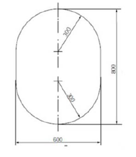
Figure LR 3.7 Vertical
Openings
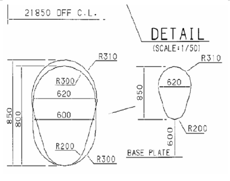
Figure LR 3.8 Alternative
Vertical Openings
LR 3.5-06 For ships complying with the requirements for type A
independent tanks, manholes will not be permitted through the secondary barrier,
except through the upper deck in regions which are above the predicted surface of
the cargo assuming total failure of the cargo tank and the ship at 30° heel port or
starboard. Alternative structural arrangement will be specially considered.
3.5.4 Access from the open weather deck to
non-hazardous areas shall be located outside the hazardous areas as defined in
chapter 10, unless the access is by means of an airlock in accordance with 3.6.
3.5.5 Turret compartments shall be arranged with two
independent means of access/egress.
3.5.6 Access from a hazardous area below the weather
deck to a non-hazardous area is not permitted.
3.6 Airlocks
3.6.1 Access between hazardous area on the open weather
deck and non-hazardous spaces shall be by means of an airlock. This shall consist of
two self-closing, substantially gastight, steel doors without any holding back
arrangements, capable of maintaining the overpressure, at least 1.5 m but no more
than 2.5 m apart. The airlock space shall be artificially ventilated from a
non-hazardous area and maintained at an overpressure to the hazardous area on the
weather deck.
3.6.2 Where spaces are protected by pressurization, the
ventilation shall be designed and installed in accordance with recognized
standardsfootnote.
3.6.3 An audible and visible alarm system to give a
warning on both sides of the airlock shall be provided. The visible alarm shall
indicate if one door is open. The audible alarm shall sound if doors on both sides
of the air lock are moved from the closed positions.
3.6.4 In ships carrying flammable products, electrical
equipment that is located in spaces protected by airlocks and not of the certified
safe type, shall be de-energized in case of loss of overpressure in the space.
3.6.5 Electrical equipment for manoeuvring, anchoring
and mooring, as well as emergency fire pumps that are located in spaces protected by
airlocks, shall be of a certified safe type.
3.6.6 The airlock space shall be monitored for cargo
vapours (see 13.6.2).
3.6.7 Subject to the requirements of the International
Convention on Load Lines in force, the door sill shall not be less than 300 mm in
height.
3.7 Bilge, ballast and oil fuel arrangements
3.7.1 Where cargo is carried in a cargo containment
system not requiring a secondary barrier, suitable drainage arrangements for the
hold spaces that are not connected with the machinery space shall be provided. Means
of detecting any leakage shall be provided.
3.7.2 Where there is a secondary barrier, suitable
drainage arrangements for dealing with any leakage into the hold or insulation
spaces through the adjacent ship structure shall be provided. The suction shall not
lead to pumps inside the machinery space. Means of detecting such leakage shall be
provided.
3.7.3 The hold or interbarrier spaces of type A
independent tank ships shall be provided with a drainage system suitable for
handling liquid cargo in the event of cargo tank leakage or rupture. Such
arrangements shall provide for the return of any cargo leakage to the liquid cargo
piping.
3.7.4 Arrangements referred to in 3.7.3 shall be
provided with a removable spool piece.
3.7.5 Ballast spaces, including wet duct keels used as
ballast piping, oil fuel tanks and non-hazardous spaces, may be connected to pumps
in the machinery spaces. Dry duct keels with ballast piping passing through may be
connected to pumps in the machinery spaces, provided the connections are led
directly to the pumps, and the discharge from the pumps is led directly overboard
with no valves or manifolds in either line that could connect the line from the duct
keel to lines serving non-hazardous spaces. Pump vents shall not be open to
machinery spaces.
LR 3.7-01 Unless specified otherwise, the requirement within 3.7.5
of the Code for Pump vents not to be open to machinery spaces need only be applied
to pumps in machinery spaces serving dry duct keels through which ballast piping
passes.
LR 3.7-02 The requirement of LR 3.7-01 is to be applied unless
specified otherwise by the National Administration.
3.8
Bow and stern loading and unloading arrangements
3.8.1 Subject to the requirements of this section and
chapter 5, cargo piping may be arranged to permit bow or stern loading and
unloading.
3.8.2 Bow or stern loading and unloading lines that are
led past accommodation spaces, service spaces or control stations shall not be used
for the transfer of products requiring a type 1G ship. Bow or stern loading and
unloading lines shall not be used for the transfer of toxic products as specified in
1.2.53, where the design pressure is above 2.5 MPa.
3.8.3 Portable arrangements shall not be permitted.
3.8.4.1 Entrances, air inlets and openings to
accommodation spaces, service spaces, machinery spaces and controls stations, shall
not face the cargo shore connection location of bow or stern loading and unloading
arrangements. They shall be located on the outboard side of the superstructure or
deckhouse at a distance of at least 4% of the length of the ship, but not less than
3 m from the end of the superstructure or deckhouse facing the cargo shore
connection location of the bow or stern loading and unloading arrangements. This
distance need not exceed 5 m.
3.8.4.2 Windows and sidescuttles facing the shore
connection location and on the sides of the superstructure or deckhouse within the
distance mentioned above shall be of the fixed (non-opening) type.
3.8.4.3 In addition, during the use of the bow or stern
loading and unloading arrangements, all doors, ports and other openings on the
corresponding superstructure or deckhouse side shall be kept closed.
3.8.4.4 Where, in the case of small ships, compliance
with 3.2.4.1 to 3.2.4.4 and 3.8.4.1 to 3.8.4.3 is not possible, the Administration
may approve relaxations from the above requirements.
3.8.5 Deck openings and air inlets and outlets to
spaces within distances of 10 m from the cargo shore connection location shall be
kept closed during the use of bow or stern loading or unloading arrangements.
3.8.6 Firefighting arrangements for the bow or stern
loading and unloading areas shall be in accordance with 11.3.1.4 and 11.4.6.
3.8.7 Means of communication between the cargo control
station and the shore connection location shall be provided and, where applicable,
certified for use in hazardous areas.
LR 3.8-01 Full details of bow and stern loading and unloading
arrangements, including fire-fighting arrangments, are to be submitted for
consideration, see also Pt 7, Ch 6 of the Rules for Ships.
LR 3.9 General
LR 3.9–01 The scantlings and arrangements of the hull structure
are to be in accordance with the appropriate Chapters of Parts 3 and 4 of the Rules
for Ships, modified as indicated in the following paragraphs. All references within
LR 3.9–02 to LR 3.26-01 are with respect to the Rules for Ships unless stated
otherwise.
LR 3.9-02 The scantlings of structural items are to be verified
by direct calculations, see LR III.5
LR 3.9–03 The following symbols used in these Rules, are defined
in Pt 3, Ch 1,6:
|
L |
= |
Rule length of ship, in metres
|
|
B |
= |
moulded breadth of ship, in metres
|
|
D |
= |
moulded depth of ship, in metres
|
|
T |
= |
moulded draught of ship, in metres
|
|
k,kL |
= |
higher tensile steel factor, see Pt 3, Ch 2,1.
|
LR 3.10 Distribution of continuous
longitudinal material
LR 3.10-01 The minimum Rule scantlings are to be maintained for
not less than 0,4L amidships, but may be required to be extended further
depending on the arrangement of the hull structure. Thereafter, the scantlings may
be tapered to the end thickness required by Pt 3, Ch 3,2.5 except where otherwise
specified. The extent of any additional material required to be incorporated in the
hull structure, and the tapering arrangements, will be specially considered.
LR 3.10-02 The scarfing arrangements at the ends of trunks and at
other abrupt changes of section are to be such as to ensure adequate continuity of
strength.
LR 3.11 Quality and grade of
material
LR 3.11-01 The materials of the hull structure are to comply with
the requirements of the Rules for the Manufacture, Testing and Certification of
Materials. The requirements of Pt 3, Ch 2 of the Rules for Ships are also to
be complied with, except as indicated otherwise, see 4.19.1 and LR 6.4.
Proposals to use materials other than steel in the hull structure will be specially
considered.
LR 3.11-02 In the determination of scantlings the higher tensile
steel factor, kL, is only to be applied when the extent of higher
tensile steel fitted is in accordance with Pt 3, Ch 3,2.6. The scantlings of
localized regions of higher tensile steel will be specially considered.
LR 3.12 Protection of steelwork
and corrosion control
LR 3.12-01 The requirements of Pt 3, Ch 2,3 are to be adopted where
applicable. Particular attention is to be given to protection in way of stainless
steel inserts and other bi-metallic connections.
LR 3.13 Assessment of longitudinal
strength
LR 3.13-01 Longitudinal strength calculations are to be made in
accordance with the requirements of Pt 3, Ch 4. Where the structural analysis of the
hull is carried out by direct calculation procedures, and these include the
assessment of longitudinal strength, full details of the assumptions made and the
calculations are to be submitted, see also LRIII.5.
LR 3.13-02 Ships intended for the carriage of liquefied gases are
to be provided with an approved loading instrument as required by Pt 3, Ch
4,8.3.
LR 3.13-03 LR may require additional longitudinal strength and
stiffness to take account of the behaviour of the hull structure and in particular
the interaction between the cargo containment system and the hull structure.
LR 3.13-04 Where a continuous rigid trunk is fitted above the
strength deck, the longitudinal material of the trunk may be taken into account when
calculating the hull section modulus, and the vertical lever, z, is to be
calculated in accordance with Pt 3, Ch 3,3.4.11. Where continuous open girders are
fitted on the deck or trunk top, they may also be taken into account when
calculating the hull section modulus as permitted by Pt 3, Ch 3,3.4.
LR 3.14 Local scantling
reduction
LR 3.14-01 Local scantling reduction factors are generally to be
in accordance with Pt 3, Ch 4,5.7.
LR 3.15 Deck plating
LR 3.15-01 The thickness of deck plating is to comply with the
requirements of Table LR 3.1 Deck plating and longitudinals together with the
hull buckling strength requirements in Pt 3, Ch 4,7. The thickness of deck plating
of the fore and aft end structures are to be not less than required by Pt 3, Ch
5,2.2 and Pt 3, Ch 6,2.2. Increased scantlings may be required where local
deflections of the structure could influence the behaviour of the cargo containment
system and in way of anti-roll chocks, anti-flotation chocks or other similar
items.
LR 3.15-02 Cross deck strips at the strength deck forming the top
of a transverse bulkhead are, in general, to have a width, w, not less
than:
In cases where a transverse bulkhead top box (or equivalent) is arranged,
a reduced width of cross deck strip may be considered.
LR 3.15-03 Cross deck strips at the strength deck are, in
general, to have a thickness, t, not less than the greatest of the
following:
(a) t = 0,012s1
(b) t = 0,00083s1  + 2,5 mm + 2,5 mm
(c) t = 10 + 0,01L mm or 12 mm whichever is the
lesser.
This thickness may be required to be increased locally in way of large
access openings.
LR 3.15-04 Where the difference between the thickness of plating inside and
outside the line of main deck openings exceeds 12 mm, a transitional plate of
thickness equivalent to the mean of the adjacent plate thickness is to be
fitted.
LR 3.15-05 Cross deck strips are to be sufficiently stiffened in
the transverse direction.
LR 3.15-06 The thickness of deck plating supporting or forming
part of the primary barrier may be required to be further increased.
Table LR 3.1 Deck plating and longitudinals
| Item, see Fig. LR 3.4
|
Requirement
|
| (1) Thickness of strength or trunk deck
plating, see Notes 1 and 2
|
The greater
of:
|
(a) t =
0,001s1 (0,059L1 + 7)
 mm mm
|
(b) t =
0,00083s1f + tc mm (but not
less than 6,5 mm) + tc mm (but not
less than 6,5 mm)
|
| (2) Thickness of upper deck,
see Notes 2, 3 and 4
|
For weather
part
|
| (a) t as for
(1)
|
| For deck
inboard
|
|
|
(b) t =
0,012s1 mm mm
|
|
|
In way of the
crown of a tank
|
|
|
(c) t =
0,004sf + 3,5 mm + 3,5 mm
|
| (3) Thickness of inner
deck
|
The greater
of:
|
| (a) LR
3.22-03
|
|
|
(b) 6,5
mm
|
|
|
In way of a
tank, not less than:
|
|
|
(c) t =
0,004sf + 2,5 mm + 2,5 mm
|
| (4) Strength or trunk deck
longitudinals and Upper deck longitudinals, see Note
3
|
Modulus, in cm3
|
Inertia, in cm4
|
| (a) Z = 0,043s k
hT1le2F1
|
-
|
| In way of the crown or bottom of a tank,
not less than
|
I = 
|
(b) 
|
|
| (5) Section modulus of inner deck
longitudinals
|
LR 3.22-03
|
| Symbols
|
| L,
k, kL, s, S as defined in
Pt 4, Ch 1,1.5.1
|
| FD as defined in Pt 3, Ch 4,5.7
|
| ρ = relative
density (specific gravity) of liquid carried in a tank but is not to
be taken less than 1,025
|
| F1 = 0,25c1
|

|
hT1 = greater of  or 1,20 m or 1,20 m
|
| h4 = tank head as defined in Pt 3, Ch
3,5
|
| le = effective length of stiffening member,
in metres, but not to be taken less than 1,5 m, see Pt 3, Ch
3,3
|
| L1 = L but need not be taken greater
than 190 m
|
| s1 = s, but not to be taken less than
the smaller of
|
| tc = 1 mm, if space is void space
|
| tc = 2 mm, if space is for ballast
water
|
f = 1,1 –
 but not to be taken greater than
1,0 but not to be taken greater than
1,0
|
| γ = see
Table LR 3.2
|
| NOTES
|
| 1. The deck
thickness is to be not less than the basic strength deck end
thickness for taper as given in Pt 3, Ch 3, Table 3.2.1 Taper
requirements for hull envelope.
|
| 2. Where
separate maximum sagging and hogging still water moments are
assigned, FD, may be based on the maximum sagging
moment.
|
| 3. For the upper
deck FD may be factored to the actual stress at
location.
|
| 4. The thickness of deck
plating forming the boundary of a ballast tank is not to be less
than that required by Table 1.4.1(3) in Pt 4, Ch 1.
|
LR 3.16 Shell plating
LR 3.16-01 The scantlings of the shell envelope are to comply
with the requirements of Table LR 3.2 Bottom shell, bilge and side shell plating
and longitudinals together with the hull buckling strength requirements in
Pt 3, Ch 4,7. Increased scantlings may be necessary to meet local strength
requirements. The scantlings of the keel, bottom and side shell plating of the fore
and aft end structures are to be not less than required by Pt 3, Ch 5,3 and Pt 3, Ch
6,3.
Table LR 3.2 Bottom shell, bilge and side shell plating and
longitudinals
| Item,
see Fig. LR 3.4
|
Requirement
|
| (1) Thickness of
bottom shell and bilge plating, see Note 1
|
The greater of:
|
| (a) Pt 4, Ch 1, Table 1.5.2
|
(b) t = 0,004sf
 mm mm
|
| (2) Thickness of
side shell plating and sheerstrake, see Note 1
|
The greater of:
|
| (a) Pt 4, Ch 1, Table 1.5.3
|
(b) t = 0,004sf
 mm mm
|
| 3) Bottom and
bilge longitudinals
|
The greater of:
|
| (a) Z = γ1 s k hT2 le
2 F1
cm3
|
| (b) Z = γ1 s k hT3 le
2 F1 Fsb
cm3
|
(c) Z = 
|
| (4) Side
longitudinals in way of double skin tanks or deep tanks
|
The greater of:
|
| (a) Z as from (5)
|
| (b) Z from (3) (c)
|
| (5) Side
longitudinals in way of dry spaces
|
The lesser of:
|
| (a) Z = 0,056s k hT1 le
2 F1 Fs
cm3
|
| (b) Z from (3) (a) evaluated using s, k, le
for the longitudinal under consideration and the remaining
parameters evaluated at the base line
|
| Symbols
|
| D, L, k, kL, s, S
as defined in Pt 4, Ch 1,1.5.1
|
|
D1
|
= |
D2
, in metres, but is not to be taken less than 10 and
need not be taken greater than 16 |
|
|
D2
|
= |
D, in metres, but need not be taken greater than
1,6T
|
|
|
FB, FD
|
= |
as defined in Pt 3, Ch 4,5.7 |
|
|
ρ
|
= |
relative density (specific gravity) of
liquid carried in a tank but is not to be taken less
than 1,025 |
|
|
|
|
hT1
|
= |
- Cw
 , in metres, for longitudinals
above the waterline, at draught T, where , in metres, for longitudinals
above the waterline, at draught T, where  is not to be taken less than is not to be taken less than 
- for Type 'B-60' ships and the
greater of
 or 1,20 m for Type 'B' ships or 1,20 m for Type 'B' ships
|
| = |
 , in metres, for longitudinals
below the waterline, at draught T , in metres, for longitudinals
below the waterline, at draught T- hT1
need not exceed 0,86
 for F1
≤ 0,14 and for F1
≤ 0,14 and

|
|
|
hT2
|
= |
T + 0,5Cw
, in metres, but need not be taken greater than
1,2T
|
|
|
hT3
|
= |
h4
– 0,35T, at the base line, in metres |
| = |
h4
, at and above 0,35T from the base line, in
metres, intermediate values by linear interpolation |
|
|
h4
|
= |
for plating the distance from a point one
third of the height of the plate above its lower edge to
the top of the tank, or half the distance to the top of
the overflow, whichever is the greater |
|
|
h4
|
= |
for stiffeners, the distance from the
middle of the effective length to the top of the tank,
or half the distance to the top of the overflow,
whichever is the greater |
|
|
h5
|
= |
vertical distance, in metres, from
longitudinal to deck at depth, D2
|
|
|
h6
|
= |
vertical distance, in metres, from the
waterline at draught T to the longitudinal under
consideration |
|
|
Fsb
|
= |
fatigue factor for bottom
longitudinals |
| = |
0,5 (1 + Fs
) |
|
| Where Fs is to
be calculated at 0,6D2 above base.
|
Fs
is a fatigue factor for side longitudinals to be taken as
follows:
- (a) For built sections and rolled angle
bars
-
 at 0,6D2
above the base line at 0,6D2
above the base line
- = 1,0 at D2
and above, and Fsb
at the base line intermediate values by linear
interpolation
- (b) For flat bars and bulb plates
Fs may be taken as 0,5
|
|
bf1
|
= |
the minimum distance, in mm, from the edge
of the face plate of the side longitudinal under
consideration to the centre of the web plate, see
Fig. LR 3.5 |
|
|
γ |
= |
1,4 for rolled or built sections and double
plate bulkheads |
| = |
1,6 for flat bars |
|
|
ω |
= |
as defined in Pt 4, Ch 1, Table 1.9.1 |
|
|
Cw
|
= |
7,71 x 10⁻²
Le–0,0044L where L is not to be
taken greater than 227 |
|
|
|
|
|
|
le1
|
= |
le
in metres, but is not to be taken less than 2,5 m
and need not be taken greater than 5,0 m |
|
|
le
|
= |
effective length of stiffening member, in
metres, but is not to be taken less than 1,5 m except in
way of the centre girder brackets required by Pt 4, Ch
1,8.5.3 where a minimum span of 1,25 may be used |
|
|
|
|
Fλ |
= |
1,0 for L ≤ 200 m |
| = |
[1,0 + 0,0023(L-200)] for L > 200 m |
|
| NOTES
|
|
1. The bottom shell, bilge and side
shell plating thickness is to be not less than the basic shell end
thickness for taper as given in Pt 3, Ch 3, Table 3.2.1 Taper
requirements for hull envelope.
|
|
2. The ratio of the web depth,
dw
, to web thickness, t, is to comply with the following
requirements:
|
(a) Built-up profiles and rolled
angles: 
|
| (b) Flat bars:
 when continuous at bulkheads when continuous at bulkheads
 when non-continuous at bulkheads when non-continuous at bulkheads
|
|
3. Where struts are fitted midway
between transverses in way of double bottom tanks, or double skin
construction, the modulus of the bottom or side longitudinals may be
reduced by 50k per cent from that obtained from the locations
(3), (4), or (5) as applicable.
|
|
4. Where the bilge radius exceeds the
Rule height of a double bottom the modulus of the longitudinal above
this nominal height is to be derived from the location (4) or (5) as
applicable.
|
|
5. Where no bilge longitudinals are
fitted and bilge brackets are required by location (3) in Pt 4, Ch
1, Table 1.5.2, at least two brackets are to be fitted.
|
LR 3.17 Longitudinal and
transverse framing and deck beams
LR 3.17-01 The scantlings of deck longitudinals are to comply
with the requirements of Table LR 3.1 together with the hull buckling strength
requirements in Pt 3, Ch 4,7. The scantlings of deck longitudinals of the fore and
aft end structures are to be not less than required by Pt 3, Ch 5,2.3 and Ch 6,2.3
with h0 derived as a dry cargo ship. The scantlings for topside
tank structure are to be in accordance with Pt 4, Ch 7,7.
LR 3.17-02 The scantlings for shell framing are to comply with the
requirements of Table LR 3.2 together with the hull buckling strength requirements
in Pt 3, Ch 4,7. The scantlings of shell framing for transversely framed ships are
not to be less than Pt 4, Ch 1,6. The scantlings of the keel, bottom and side shell
framing of the fore and aft end structures are to be not less than required by Pt 3,
Ch 5,4 and Pt 3, Ch 6,4. In the application of Pt 3, Ch 5,4.3 and Ch 6,4.3 and Pt 4,
Ch 1,6.3, the following are also to be complied with for single sided ships fitted
with topside tanks:
-
When deriving the section modulus of main frames T is
to be taken not less than 0,7D1 in the calculation of h6
and hT1 and the end connection factor C is to be taken as
3.4.
-
Brackets are to be fitted at the lower and upper ends of
transverse main frames.
-
The lengths of the arms of the end brackets are not to be
less than as required by Pt 3, Ch 10,3.4.
-
Double continuous welding is to be adopted for the
connections of frames and brackets to side shell, hopper and topside
tank plating and web to face plates. For weld factors, see Pt 3,
Ch 10, Table 10.2.1, Table 10.2.2 and Table 10.2.4.
Where the hull form is such that an effective fillet weld
cannot be made, edge preparation of the web of the frame and bracket may
be required, in order to ensure the required efficiency of the weld
connection.
-
Continuity of the frames is to be maintained by supporting
brackets in the topside and hopper tanks, see Fig. LR 3.1
-
The design of end connections and their supporting structure
is to be such as to provide adequate resistance to rotation and
displacement of the joint.
The size and arrangement of stiffening of the supporting
brackets will be specially considered. Where the toe of the hold frame
bracket is situated on or in close proximity to the first longitudinal
from the shell of the hopper or topside tank sloped bulkheads, the
supporting brackets are to be extended to the next longitudinal. This
extension is to be achieved by enlarging the supporting bracket or by
fitting an intercostal flat bar stiffener the same depth as the
longitudinal and connected to the webs of the longitudinals.
1. The requirements are to be maintained throughout the cargo
hold region. However, in the forward and aft cargo holds where the shape
becomes finer because of the ship form, increased requirements may be
necessary and each case will be specially considered.
-
In way of the foremost hold, side frames of asymmetric
section are to be effectively supported by intercostal brackets,
see Fig. LR 3.2.
-
The hold side shell frame adjacent to the bulkhead at fore
end of No. 1 hold is to be suitably strengthened. As an alternative, at
least two supporting structures are to be fitted which align with the
forepeak stringers or flats, see Fig. LR 3.3. The supporting
structures are to have adequate cross-sectional shear resisting area at
their connections to the hold frame.
The arrangements at the intersections of continuous
secondary and primary members are to comply with the requirements of Pt
3, Ch 10,5 using the requirements for other ship types with the Rule
scantling derivation heads in their assessment.
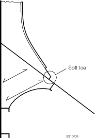
Fig. LR 3.1 - Supporting
brackets in topside and hopper tanks
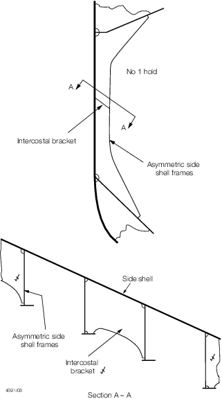
Fig. LR 3.2 - Typical
arrangement of intercostal brackets supporting asymmetric side shell frames
in No.1 hold
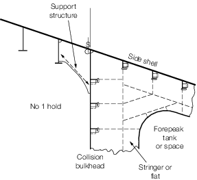
Fig. LR 3.3 - Hold frame
supporting structures at fore end of No.1 cargo hold
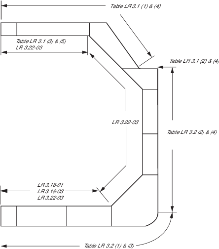
Fig. LR 3.4 - Itemisation
of parts
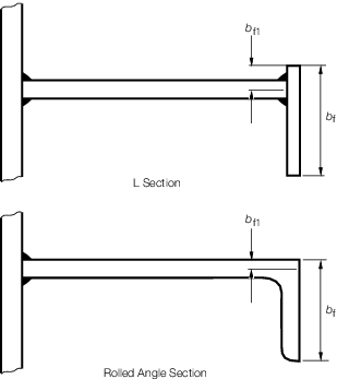
Fig. LR 3.5 - Definition
of bf and bf1
LR 3.18 Double bottom
LR 3.18-01 The extent and depth of double bottom is to be not less
than required by Chapters 2 and 3 of these Rules for the ship type and intended
cargoes. The scantlings and arrangements are also to comply with Pt 4, Ch 1,8, Pt 3,
Ch 5,5 and Pt 3, Ch 6,5 of the Rules for Ships. Where the structural arrangements
are considered such as to necessitate it, LR may require further verification by
direct calculations.
The thickness of the inner bottom plating may be required to be increased
locally in way of tank support structure. Where the double bottom is common with
wing or side ballast tanks, the scantlings of the inner bottom are to be not less
than that given by LR 3.22-03(d). At the intersection of inner bottom and hopper
plating, collars are to be fitted to any unavoidable scallops in the floors, to
minimise stress concentrations in these regions.
LR 3.18-02 The depth, at centreline, of the double bottom of ships
with independent spherical Type B tanks is to be determined by direct calculation
taking into account the access requirements of Ch 3,3.5.3. The inner bottom may be
sloped downwards towards the ship’s centreline such that the minimum double bottom
depth is not less than 0,7dDB or 1000 mm, whichever is the greater, where
dDB is the Rule depth, in mm, derived from Pt 4, Ch 1,8 of the Rules for
Ships for general cargo ships.
LR 3.18-03 Where the inner bottom forms part of the cargo
containment system or provides direct support to the containment system, the
requirements of LR 3.22-03 are to be applied. The scantlings are also to be
sufficient to meet the requirements of the containment system design.
LR 3.19 Strengthening of bottom
forward
LR 3.19-01 The bottom forward is to be strengthened as required
by Pt 3, Ch 5,1.5.
LR 3.20 Primary support structure
of deck
LR 3.20-01 Deck girders and transverses are to have a section
modulus not less than that required by Pt 4, Ch 1,4 and Pt 4, Ch 7,7.5 as
appropriate, but additional strengthening may be required to take account of the
pressures, loads or moments transmitted from the cargo containment system.
LR 3.20-02 Where the deck structure acts as the structural support
for the cargo containment system and the primary structure is fitted in one
direction only, the section modulus and moment inertia of the member are, in
general, to be not less than:
where
|
k |
= |
higher tensile steel factor, see Pt 3, Ch 2,1
|
|
b |
= |
the actual width of the load bearing plating supported by the
member, in metres, see Pt 3, Ch 3,3
|
|
h |
= |
the head equivalent to the loading which may be imposed, in
metres
|
|
le |
= |
effective length of the member, in metres, see Pt 3,
Ch 3,3.
|
LR 3.21 Transverse
bulkheads
LR 3.21-01 Where the cargo containment system incorporates
independent tanks, and provision for floodable cofferdams between holds is not made
(see LR 3.1–02), the scantlings of bulkhead plating and stiffening are to
be as required for a watertight bulkhead by Pt 4, Ch 1,9.
LR 3.21-02 Where floodable cofferdams are fitted, the scantlings
are to be as required for a deep tank bulkhead by Pt 4, Ch 1,9.
LR 3.21-03 Where the bulkhead forms part of the cargo containment
system or provides direct support to the containment system, the scantlings are to
be sufficient to meet the requirements of the containment system design and the
loads imposed by it. In addition, where the transverse bulkheads are directly loaded
by the cargo the requirements of LR 3.21-04 are to be applied. In this case, the
transverse bulkheads should be able to withstand a collision force corresponding to
one half the weight of the cargo in the forward direction and one quarter the weight
of the tank and cargo in the aft direction without deformation likely to endanger
the tank structure, see also 4.15.1. The scantlings are to be in accordance
with the requirements of LR 3.21-06. The scantlings are also to comply with Pt 4, Ch
1,9 as required for a watertight bulkhead.
LR 3.21-04 Scantlings of transverse bulkheads providing direct
support to the containment system are to comply with the following, see also
LR 3.21-05:
- Boundary plating
The thickness, t, of plating
forming the boundaries of cargo tanks is to be not less
but not less than 7,5 mm
- Rolled or built stiffeners
The section modulus of
rolled or built stiffeners on plating forming tank boundaries is to be not
less than:
where
- Peq = the internal pressure head, in
MPa, as derived from 4.28.1.1 of these Rules
- s,k,le, f = as defined in LR
3.22-03
- γ, ω1, ω2 = as defined in
Table 1.9.1 in Pt 4, Ch 1.
LR 3.21-05 Where it is proposed to use higher tensile steel for
secondary stiffeners, the effect on fatigue performance of the connection details
between secondary members and the primary supporting structure should be taken into
consideration. The containment design should also be adequate to cope with the
increased deformations expected with the use of higher tensile steel.
LR 3.21-06 When determining scantlings for the transverse
bulkhead in dry space cofferdams, due to the loads arising from the collision case
mentioned in LR 3.21-03, the following requirements are to be complied with. An
additional 1 mm is to be added to the thickness derived below if the cofferdam is
floodable.
- The plating:
where
s, f and
k are as defined in LR 3.22-03
PCOLL = collision pressure, in MPa, as derived from
LR 3.21-03, see also 4.15.1.
- Rolled or built stiffeners:
where
γ = 1,3.
LR 3.21-07 The local and overall strength of the bulkhead may be required to
be increased in way of the tank supporting structure, collision chocks,
anti-flotation chocks or similar items.
LR 3.21-08 Where horizontal and vertical girders are used to
support the bulkhead, the bulkhead scantlings may be determined using direct
calculation procedures. The assumptions made and the calculations are to be
submitted.
LR 3.22 Longitudinal bulkheads and inner hull
LR 3.22-01 Longitudinal bulkheads and the inner hull, where these
items are fitted, are to comply with the requirements given above for transverse
bulkheads.
LR 3.22-02 In addition, the scantlings of plating and
longitudinal framing are to be sufficient to meet the longitudinal strength and
shear force requirements given in LR 3.13-01and Pt 3, Ch 4. Inner bottom plating and
longitudinals are to meet the requirements of Pt 4, Ch 1,8.4.
LR 3.22-03 Where the longitudinal bulkhead provides direct
support for the containment system, a structural analysis of the hull structure will
be required using direct calculation procedures which are to be agreed with LR at as
early a stage as possible.
When determining scantlings for the inner hull, the following
requirements are to be complied with:
- Plating:
The thickness of plating should be not less
than:
- where
|
t |
= |
derived plate thickness, in mm |
|
s |
= |
stiffener spacing, in mm |
|
k |
= |
higher tensile steel factor, see Pt 3, Ch 2,1 |
|
Peq |
= |
the internal pressure head, in MPa, as derived from
4.28.1.1 of these Rules |
|
f |
= |
 but need not exceed 1,0 but need not exceed 1,0 |
|
S |
= |
overall length of stiffeners, in metres, between support
points. |
- Rolled or built stiffeners:
The section modulus of
rolled or built stiffeners should not be less than:
Z = 4,7s k
Peq
le2F1 cm3
- where
|
k |
= |
higher tensile steel factor, see Pt 3, Ch
2,1 |
|
Peq |
= |
the internal pressure head, in MPa, as derived from
4.28.1.1 of these Rules, but is not to be taken as less than
 MPa or (0,0001L1 +
0,007) MPa, whichever is the greater MPa or (0,0001L1 +
0,007) MPa, whichever is the greater |
|
L1 |
= |
L, but need not be taken as greater than 190
m |
|
s |
= |
stiffener spacing, in mm |
|
le |
= |
effective length of stiffeners, in metres |
|
c |
= |
 at deck, see definition of
depth D at deck, see definition of
depth D |
| = |
1,0 at  |
| = |
 at base line at base line |
- Intermediate values of c are to be obtained by
linear interpolation
|
F1 |
= |
 , for longitudinals above , for longitudinals above
 |
| = |
 , for longitudinals below , for longitudinals below
 |
- but is not to be taken as less than 0,12
|
h |
= |
distance of longitudinal below deck at side, in
metres |
| = |
distance of longitudinal below trunk deck at side, in
metres, for ships fitted with a trunk deck |
|
D |
= |
depth of ship, in metres, as defined in Pt 3, Ch
1,6.1.4
|
| = |
depth of ship to trunk deck at side for ships fitted
with trunk deck |
|
FD |
= |
as defined in Pt 3, Ch 4,5 |
|
FB |
= |
as defined in Pt 3, Ch 4,5 |
- Connection of inner hull longitudinals to primary members:
In considering these connections, the requirements of Pt 3, Ch
10,5.2 are to be applied as for oil tankers taking account of the dynamic
pressure heads determined by 4.28.1.1 of these Rules.
- Where the inner hull is common with wing or side ballast tanks the
scantlings of the inner hull are to be not less than:
Plating:
but not less than 7,5 mm
Rolled or built
stiffeners:
where
s, f, k, ρ,
h4, γ, ω1 and ω2 are as defined in Table LR 3.2.
LR 3.23 Primary support structure
of the side shell and inner hull
LR 3.23-01 Transverses supporting side longitudinals are to be
arranged in line with the floors in the double bottom to ensure continuity of
transverse strength. The section modulus of side transverses and moment inertia are,
in general, to be not less than:
Z = 48ρ k S h le2 cm3
where
|
ρ |
= |
as defined in Pt 4, Ch 1,1.5
|
|
k |
= |
higher tensile steel factor, see Pt 3, Ch 2,1
|
|
S |
= |
overall length of stiffener, in metres, between support
points
|
|
h |
= |
Peq x 10,2
|
|
Peq |
= |
the internal pressure head, in MPa, as derived from 4.28.1.1
of these Rules
|
|
le |
= |
effective length of stiffening member, in metres, see
Pt 3, Ch 3,3.
|
LR 3.24 Strengthening for
navigation in ice
LR 3.24-01 Where an ice class notation is desired, additional
strengthening is to be fitted, as required by Pt 8.
LR 3.25 Strengthening for wave
impact loads
LR 3.25-01 The side structure in the forward portion of the hull
is to be strengthened against wave impact pressure in accordance with Pt 4, Ch 2,4.3
and 5.2. The side structure requirements taken from Pt 4, Ch 2,5.2 must in no case
be taken as less than those required by these Rules.
LR 3.26 Additional
requirements
LR 3.26-01 The scantlings and arrangements of ventilators, air
pipes and discharges, closing arrangements and ship control systems are to comply
with the appropriate Chapters of Parts 3 and 4 of the Rules for Ships, except where
required otherwise by these Rules.
|