Figures 1 to 5 show photographs of the equipment
as assembled ready for test. Detailed drawings and a parts list are
available from the IMO Secretariat. These provide engineering information
necessary for the fabrication of the main frame, specimen holders,
stack and other necessary parts of the equipment.
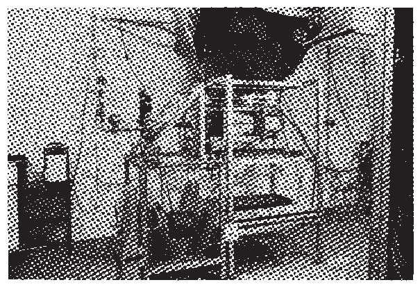
Figure 1 General view of the apparatus
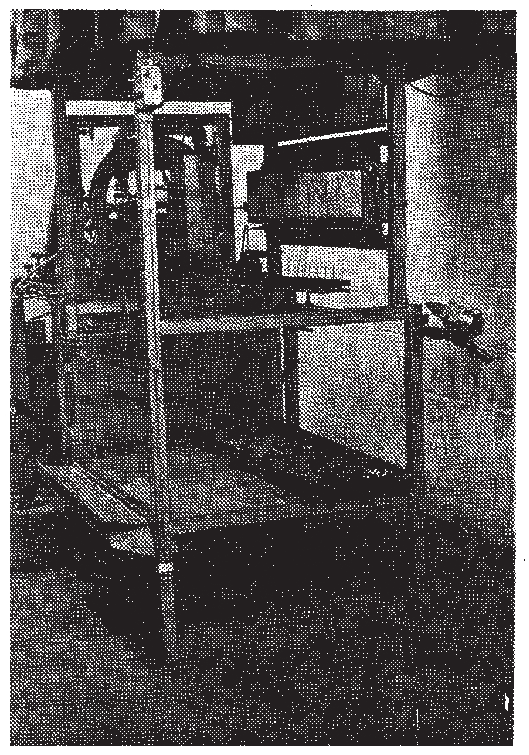
Figure 2 View from specimen end
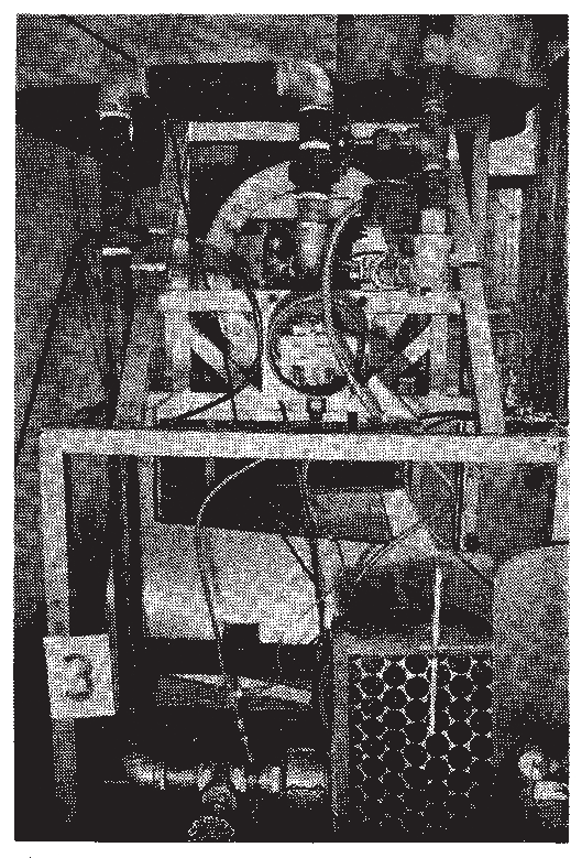
Figure 3 View from radiant panel end
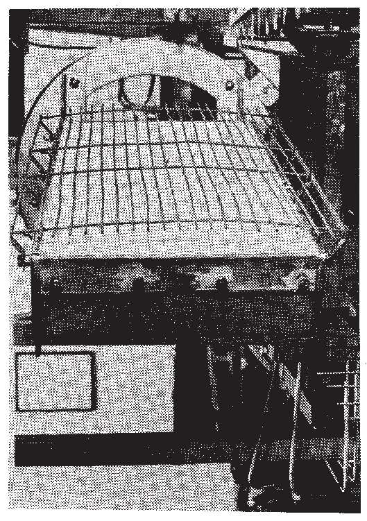
Figure 4 Radiant panel with reverberatory wires viewed through specimen mount
frame
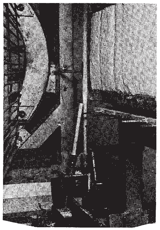
Figure 5 Pilot burner and mount
1.1 Brief parts list for the test equipment assembly
includes:
-
.1 The main frame (Figure
1) which comprises two separate sections, the burner frame
and the specimen support frame. These two units are bolted together
with threaded rods permitting flexibility in mechanical alignment.
-
.2 Specimen holders which provide for support
of the specimens during test. At least two of these are required.
Three prevent delays resulting from required cooling of holders prior
to mounting specimens.
-
.3 A specimen fume stack fabricated of stainless
steel sheet of 0.5 ± 0.05 mm thickness complete with gas and
stack metal compensating thermocouples.
-
.4 The radiant panel which has radiating surface
dimensions of 280 mm x 483 mm. It has been specially fabricated for
use with this equipment through use of commercially available porous
refractory tiles.
-
.5 The blower for combustion air supply, radiant
panel, air flow metering device, gas control valves, pressure reducer
and safety controls which are all mounted on the burner frame (Figure 3). Requirements are summarized
below:
-
.5.1 Air supply of about 30 m3/h at
a pressure sufficient to overcome the friction losses through the
line, metering device and radiant panel. The radiant panel drop amounts
to only a few millimetres of water.
-
.5.2 The gas used may be either natural gas or
methane. The use of gas other than methane or natural gas is not recommendedfootnote, although with changes in panel-specimen
spacing, it is possible to use the equipment with propane at flux
levels of 50 kW/m2. A pressure regulator should be provided
to maintain a constant supply pressure. Gas is controlled by a manually
adjusted needle valve. No venturi mixer is necessary. Safety devices
include an electrically operated shutoff valve to prevent gas flow
in the event of electric power failure, air pressure failure and loss
of heat at the burner surface. The gas flow requirements are roughly
1.0 m3/h to 3.7 m3/h for natural gas or methane
at a pressure to overcome line pressure losses.
-
.6 The specimen holder, pilot flame holder, fume
stack, flame front viewing rakes, radiation pyrometer and mirror are
all assembled on the specimen support frame. The arrangement of parts
on this frame is shown in Figures 1 and 2.
-
.7 A dummy specimen approximately 20 mm thick.
made of non-combustible refractory board of 800 ± 100 kg/m3 density
should be continuously mounted on the apparatus in the position of
the specimen during operation of the equipment. This dummy specimen
should only be removed when a test specimen is to be inserted.