Preamble
1 The following information is provided for consideration by, and
guidance to, the users of these guidelines:
-
.1 To ensure uniformity of application, typical benchmark scenarios and
relevant data are specified in the guidelines. Therefore, the aim of the
analysis is to assess the performance of the ship with regard to the
benchmark scenarios rather than simulating an actual emergency.
-
.2 Although the approach is, from a theoretical and mathematical point of
view, sufficiently developed to deal with realistic simulations of
evacuation on board ships, there is still a shortfall in the amount of
verification data and practical experience on its application. When suitable
information is provided by Member Governments, the Organization should
reappraise the figures, parameters, benchmark scenarios and performance
standards defined in the interim guidelines.
-
.3 Almost all the data and parameters given in the guidelines are based on
well-documented data coming from civil building experience. The data and
results from ongoing research and development show the importance of such
data for improving the interim guidelines. Nevertheless, the simulation of
these benchmark scenarios are expected to improve ship design by identifying
inadequate escape arrangements, congestion points and optimizing evacuation
arrangements, thereby significantly enhancing safety.
2 For the above considerations, it is recommended that:
-
.1 the evacuation analysis be carried out as indicated in the guidelines, in
particular using the scenarios and parameters provided;
-
.2 the objective should be to assess the evacuation process through benchmark
cases rather than trying to model the evacuation in real emergency
conditions;
-
.3 application of the guidelines to analyse actual events to the greatest
extent possible, where passengers were called to assembly stations during a
drill or where a passenger ship was actually evacuated under emergency
conditions, would be beneficial in validating the guidelines;
-
.4 the aim of the evacuation analysis for existing passenger ships should be
to identify congestion points and/or critical areas and to provide
recommendations as to where these points and critical areas are located on
board; and
-
.5 keeping in mind that it is the company's responsibility to ensure
passenger and crew safety by means of operational measures, if the result of
an analysis, conducted on an existing passenger ship shows that the maximum
allowable evacuation duration has been exceeded, then the company should
ensure that suitable operational measures (e.g. updates of the onboard
emergency procedures, improved signage, emergency preparedness of the crew,
etc.) are implemented.
1 General
The purpose of this part of the guidelines is to present the methodology
for conducting an evacuation analysis and, in particular, to:
-
.1 confirm that the performance standards set out in these guidelines can be
met;
-
.2 identify and eliminate, as far as practicable, congestion which may
develop during an abandonment, due to normal movement of passengers and crew
along escape routes, taking into account the possibility that crew may need
to move along these routes in a direction opposite the movement of
passengers;
-
.3 demonstrate that escape arrangements are sufficiently flexible to provide
for the possibility that certain escape routes, assembly stations,
embarkation stations or survival craft may be unavailable as a result of a
casualty;
-
.4 identify areas of intense counter and cross flows; and
-
.5 provide information gained by the evacuation analysis to the
operators.
2 Definitions
2.1 Persons load is the number of persons considered in the means
of escape calculations contained in chapter 13 of the International Code for Fire
Safety Systems (FSS Code) (resolution MSC.98(73)).
2.2 Response duration (R) is the duration it takes for people to
react to the situation. This duration begins upon initial notification (e.g. alarm)
of an emergency and ends when the passenger has accepted the situation and begins to
move towards an assembly station.
2.3 Individual travel duration is the duration incurred by an
individual in moving from its starting location to reach the assembly station.
2.4 Individual assembly duration is the sum of the individual
response and the individual travel duration.
2.5 Total assembly duration (tA) is the maximum
individual assembly duration.
2.6 Total travel duration (T) is the duration it takes for all
persons on board to move from where they are upon notification to the assembly
stations.
2.7 Embarkation and launching duration (E+L) is the duration
required to provide for abandonment by the total number of persons on board,
starting from the time the abandon ship signal is given after all persons have been
assembled, with lifejackets donned.
3 Method of evaluation
The steps in the evacuation analysis are specified as below.
3.1 Description of the system:
3.2 Common assumptions
This method of estimating the evacuation duration is based on several
idealized benchmark scenarios and the following assumptions are made:
-
.1 passengers and crew will evacuate via the main escape route towards their
assigned assembly station, as referred to in SOLAS regulation II-2/13;
-
.2 passenger load and initial distribution are based on chapter 13 of the
FSS Code;
-
.3 full availability of escape arrangements is considered, unless otherwise
stated;
-
.4 assisting crew will immediately be at the evacuation duty locations ready
to assist the passengers;
-
.5 smoke, heat and toxic fire products are not considered to impact
passenger/crew performance;
-
.6 family group behaviour is not considered; and
-
.7 ship motion, heel, and trim are not considered
4 Scenarios to be considered
4.1 As a minimum, four scenarios (cases 1 to 4) should be considered for
the analysis as follows. If more detailed data considering the crew distribution is
available, it may be used.
-
.1 case 1 (primary evacuation case, night) and case 2 (primary evacuation
case, day) in accordance with chapter 13 of the FSS
Code.
-
.2 case 3 (secondary evacuation cases, night) and case 4 (secondary
evacuation cases, day). In these cases only the main vertical zone, which
generates the longest individual assembly duration, is further investigated.
These cases utilize the same population demographics as the primary
evacuation cases. The following are two alternatives that should be
considered for both cases 3 and 4. For ro-ro passenger ships, alternative 1
should be the preferred option:
-
.1 alternative 1: one complete run of the stairways having largest
capacity previously used within the identified main vertical zone is
considered unavailable for the simulation; or
-
.2 alternative 2: 50% of the persons in one of the main vertical
zones neighbouring the identified main vertical zone are forced to
move into the zone and to proceed to the relevant assembly station.
The neighbouring zone with the largest population should be
selected.
4.2 The following additional scenarios may be considered as appropriate:
-
.1 case 5 (Open Deck): If an open deck is outfitted for use by passengers and
its gross deck surface area is larger than 400 m² or accommodates more than
200 persons, the following, additional day case should be analysed: All
persons are to be distributed as defined in the primary day case (case 2)
considering the open deck as an additional public space with an initial
density of 0.5 persons/m², calculated using the gross deck surface area.
-
.2 case 6 (Embarkation): If separate embarkation and assembly stations are
employed, an analysis of travel duration from assembly station to the entry
point of LSA should be taken into account in the process of determining
embarkation and launching duration (E+L). All persons which the ship is
certified to carry are initially distributed according to the designated
capacities of the assembly stations. The persons will move to the entry
point of LSA according to the operator's procedures and designated routes.
The time for boarding the LSA is determined during LSA prototype test and
thus need not be addressed in detail in the simulation. However, congestion
directly in front of the LSA should be considered as part of the simulation.
These congestions need to be considered as blockage or obstacle for
passenger and crew passing, i.e. generated with a LSA entry flow rate equal
to the one observed during the LSA test.
4.3 If the total number of persons on board calculated, as indicated in the above
cases, exceeds the maximum number of persons the ship will be certified to carry,
the initial distribution of people should be scaled down so that the total number of
persons is equal to what the ship will be certified to carry.
5 Performance standards
5.1 The following performance standards, as illustrated in figure 5.1, should be
complied with:
5.2 In performance standard (1):
-
.1 for ro-ro passenger ships, n = 60; and
-
.2 for passenger ships other than ro-ro passenger ships, n = 60 if the ship
has no more than three main vertical zones; and 80, if the ship has more
than three main vertical zones.
5.3 Performance standard (2) complies with SOLAS
regulation III/21.1.3.
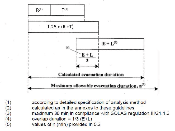
Figure 5.1
5.4 E + L should be calculated separately based upon:
-
.1 results of full scale trials on similar ships and evacuation systems;
-
.2 results of a simulation based embarkation analysis; or
-
.3 data provided by the manufacturers. However, in this case, the method of
calculation should be documented, including the value of correction factor
used.
The embarkation and launching duration (E+L) should be clearly documented to be
available in case of change of LSA.
5.5 For cases where neither of the three above methods can be used, (E+L) should be
assumed equal to 30 min.
6 Documentation
The documentation of the analysis should report on the following items:
-
.1 basic assumptions for the analysis;
-
.2 schematic representation of the layout of the zones subjected to the
analysis;
-
.3 initial distribution of persons for each considered scenario;
-
.4 methodology used for the analysis if different from these guidelines;
-
.5 details of the calculations;
-
.6 total evacuation duration;
-
.7 identified congestion points; and
-
.8 identified areas of counter and crossing flows.
7 Corrective actions
7.1 For new ships, if the total evacuation duration calculated is in excess of the
allowed total evacuation duration, corrective actions should be considered at the
design stage by suitably modifying the arrangements affecting the evacuation system
in order to reach an acceptable total evacuation duration.
7.2 For existing ships, if the total evacuation duration calculated is in excess of
the allowed total evacuation duration, onboard evacuation procedures should be
reviewed with a view toward taking appropriate actions which would reduce congestion
which may be experienced in locations as indicated by the analysis.