3
Construction.
The construction and assembly of the device should be in accordance with tables A.2 to
A.5, figures A.1 to A.19 and figures A.21 to A.36. A tolerance of ± 6 mm is used
throughout for fabric cutting and stitching assembly. A tolerance of ± 6 mm is also used
for foam cutting, however, the buoyancy requirements of table A.3 should be met.
3.1 Seams
3.1.1 The seam allowances are 13 mm, unless otherwise specified. All structural seams
use a lock type stitch so that the seam will not unravel when a force is applied in the
direction of the seam on any of the threads forming the stitch. Stitching should have a
density of 7 to 12 stitches per 25 mm of stitch length. The box-X stitching on the
webbing is 15 mm x 18 mm, unless otherwise specified. The bar-tack stitching on the
webbing is 15 mm x 2 mm.
3.1.2 On the closing seam of the back section of the outer and inside cover, the cut
ends of the fabric are turned under and stitched so that the fabric will not ravel. The
cut ends of webbing should be heat-sealed.
3.1.3 Tabs on the ends of the waist belt are formed by turning under 40 mm of material
twice and stitching 19 mm from the end of the folds with box-X or bar tack stitching.
3.1.4 The zippers are set to the fabric by turning under the raw edge of the fabric 13
mm, aligning the fold with the centre of the closed zipper, and topstitching through
both layers of fabric and the zipper tape. The stitch line should be far enough from the
zipper teeth or coil so as not to interfere with the operation of the zipper.
3.2 Assembling the fabric cover
The fabric cover is assembled as described below, with the dimensions described in
figures A.31 through A.33 and table A.4.
3.2.1 Assembling the inside cover
3.2.1.1 Attach the interior fabric retainers for foam inserts 1 (component 1.7) to the
"wrong" (interior) side on each lobe of the inside cover fabric (component 1.3).
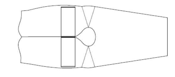
Figure A.1 – Location of Interior fabric retainers
3.2.1.2 Sew the hook and loop fasteners (component 4) to opposing sides of
the interior fabric retainers for foam inserts 2 (component 1.8) as shown in figure
A.2.
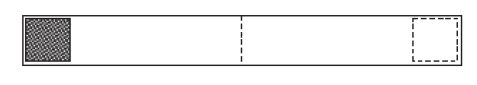
Figure A.2 – Orientation of hook and loop fasteners
3.2.1.3 Fold the interior fabric retainers for foam inserts 2 (component 1.8) in half
and sew to the inside edge seam allowance of the "wrong" (interior) side of the inside
cover fabric (component 1.3). Sew one fabric retainer to each lobe of the front cover
fabric with the hook and loop fasteners (component 4) facing upward and oriented toward
the outer edge of the inside cover fabric. Turn the bottom edge of the back cover up 13
mm and topstitch.
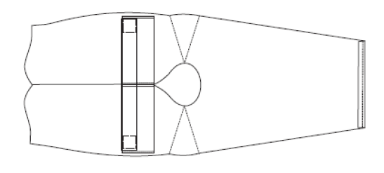
Figure A.3 – Location of fabric retainers
3.2.1.4 Attach one 89 mm black belt-loop webbing (component 3.5) to each
lobe of the "right" (exterior) side of the inside cover fabric. Join the shoulder
darts.
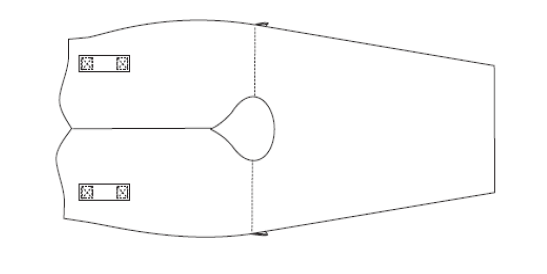
Figure A.4 – Completed inside cover
3.2.2 Assembling the collar cover
3.2.2.1 Attach the yellow collar attachment webbing (component 3.6) to the inside collar
cover (component 1.5), placing one reinforcement patch (component 1.6) under the fabric,
with a tack on each side, as in figure A.5. The webbing should be centred on the fabric,
creating a 254 mm loop measured from the edge of one tack to the edge of the other.
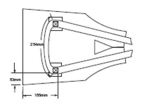
Figure A.5 – Collar attachment on collar cover
3.2.2.2 Sew the 280 mm zipper (component 6.5) to the inside and outer collar cover
fabric (component 1.5) as in figure A.6.
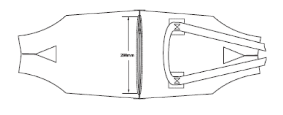
Figure A.6 – Joining the inside and outer collar cover
3.2.2.3 With the "right" (exterior) sides of the fabric together, join the sides of the
inside and outer collar cover fabric (component 1.5) at the sides and around the neck
opening. To allow access to the collar foam insert, do not join the fabric at the ends
of the zipper. Turn the collar cover right side out.
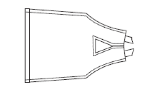
Figure A.7 – Completed collar cover
3.2.3 Assembling the outer cover
3.2.3.1 Attach one 76 mm black belt-loop webbing (component 3.4) to each shoulder on the
"right" (exterior) side of the front outer cover fabric (component 1.1) using double bar
tack stitches on each end, creating a 40 mm loop opening.
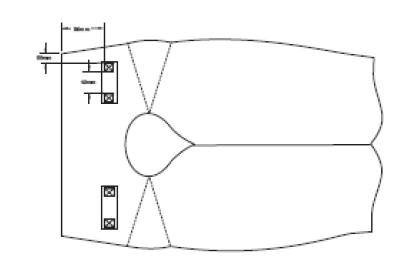
Figure A.8 – Attaching the shoulder loops
3.2.3.2 Sew the 370 mm zipper (component 6.6) to the back outer cover (component 1.2)
and front outer cover (component 1.1) as shown in figure A.9. Turn the bottom edge of
the back cover up 13 mm and topstitch.
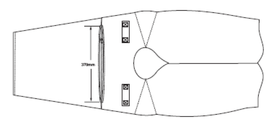
Figure A.9 – Completed outer cover
3.2.4 Joining the collar to the front outer cover
Join the shoulder darts on the front outer cover (component 1.1). Lace the yellow collar
attachment webbing (component 3.6) through the black shoulder straps (component 3.4)
with the collar loop facing toward the cover fabric. Stitch the collar cover fabric tabs
to the neck seam.
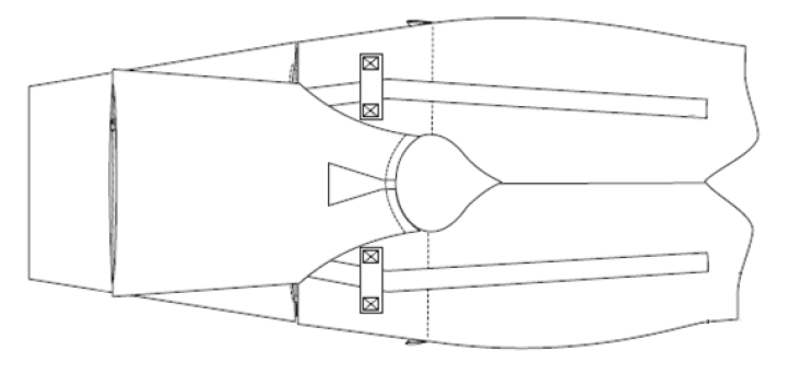
Figure A.10 – Joining the collar to the front outer cover
3.2.5 Assembling and attaching the hardware assemblies
3.2.5.1 Construct the chest strap buckle assemblies by lacing the 127 mm black chest
strap webbing (component 3.1) through the male and female buckles (component 6.1) and
stitching, as shown in figure A.11.
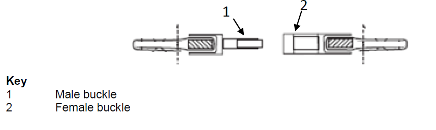
Figure A.11 – Chest strap buckle assembly
3.2.5.2 Construct the waist belt assemblies by lacing the 203 mm black waist belt
webbing (component 3.3) through the slide adjusters (component 6.2), snap hook
(component 6.3), and D-ring (component 6.4), and stitching as shown in figure A.12.
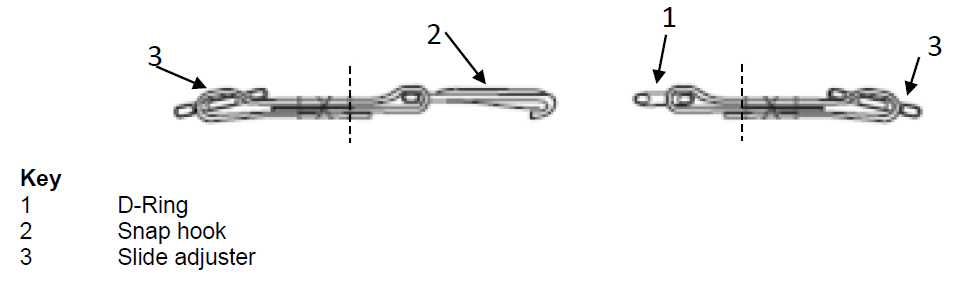
Figure A.12 – Waist belt assembly
3.2.5.3 Lace the left side yellow collar attachment webbing (component 3.6) through the
male chest strap buckle assembly. With one fabric reinforcement (component 1.6)
positioned on the "wrong" (interior) side of the front outer cover fabric (component
1.1), attach the chest strap buckle assembly to the yellow collar attachment webbing and
cover fabric with a box-X stitch. Repeat on the right side with the female chest strap
buckle assembly.
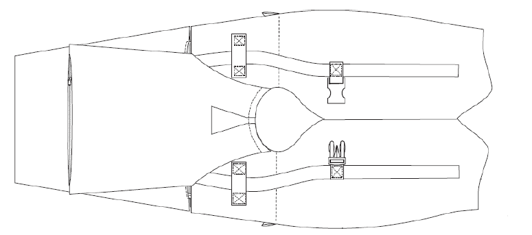
Figure A.13 – Attachment of chest strap buckle assembly
3.2.5.4 Lace the left side yellow collar attachment webbing (component 3.6) through the
snap hook waist belt assembly. Attach the waist belt assembly to the yellow collar
attachment webbing and the front outer cover fabric (component 1.1) with a box-X stitch.
Repeat on the right side with the D-ring waist belt assembly.
3.2.5.5 Stitch the yellow collar attachment webbing to cover front, between the two
buckle assemblies on each front forming a rectangle.

Figure A.14 – Chest and waist belt attachments
3.2.6 Joining the inside and outer covers
3.2.6.1 Join the inside cover fabric (component 1.3) to the front and back outer cover
fabric (components 1.1 and 1.2) at the sides by sewing a 440 mm zipper (component 6.7)
on the outside edge of each front.
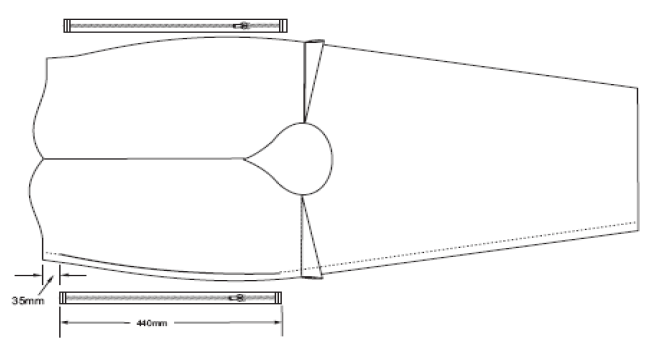
Figure A.15 – Joining the inside and outer cover fabric
3.2.6.2 Join a centre gusset (component 1.4) to the left and right lobes of the outer
cover fabric, then join to the inside cover. The seam created by joining the outside
edges should be centred on the end of the gusset with the taper of the gusset forming a
point as it approaches the neck curve, as shown in figure A.16.
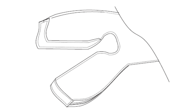
Figure A.16 – Joining the inside and outer over with the centre gusset
3.2.7 Finishing
3.2.7.1 Turn the cover right-side out. Attach the 1867 mm black waist belt webbing
(component 3.3) to the back cover with three tacks, one centred on the fabric and one on
each corner of the fabric. Tack the free ends of the webbing with a box-X with ends
double folded. Top stitch through the inside and back outer covers, 80 mm from the foam
access zipper (component 6.6).
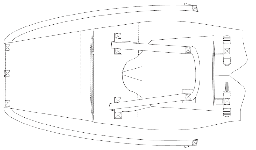
Figure A.17 – Attaching the waist belt
3.2.7.2 Lace the 1867 mm black waist belt webbing (component 3.3) through the slide
adjusters (component 6.2) on each waist belt assembly.
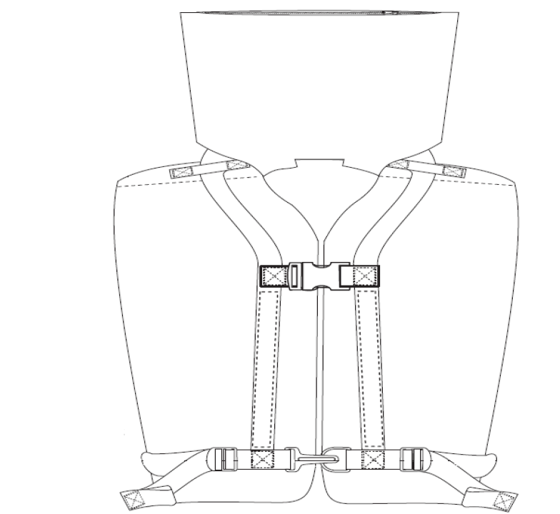
Figure A.18 – Completed RTD cover and hardware
3.3 Inserting the front foam
Slide the front foam inserts (components 2.2.1 and 2.2.2) under the interior fabric
retainers for foam inserts 1 (component 1.7). Slide the interior fabric retainers for
foam inserts 2 (component 1.8) through the slot in the front foam inserts (components
2.1.1 and 2.1.2). Wrap the interior fabric retainer for foam inserts around the foam
insert so that the retainer passes around the front of the RTD as shown in figure A.19.
Close the hook and loop fastener. Close the zipper (component 6.7).
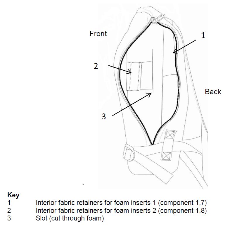
Figure A.19 – Inserting the front foam
3.4 Validation
The proper assembly of the RTD should be verified according to the Guidelines developed
by the Organizationfootnote.
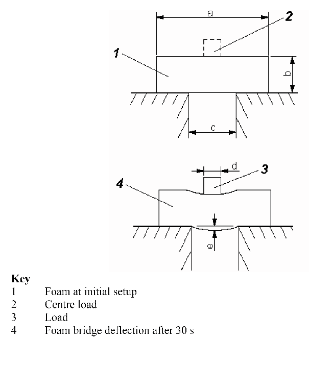
Figure A.20 – Foam bridge deflection test
Table A.1 - Specifications for the
foam bridge deflection test
|
|
Dimension shown in figure A.20
|
Load mass
|
| Foam type
|
a
(Length)
mm
|
(Not
shown)
(Width)
mm
|
b
(Thickness)
mm
|
c
(Span)
mm
|
d
(Load
width)
mm
|
e
(Deflection)
mm
|
kg
|
| Stiff
|
394
|
110
|
83
|
300
|
120
|
< 20
|
8.6
|
| Soft
|
394
|
110
|
45
|
150
|
30
|
≥ 25
|
0.75
|
Table A.2 - Parts, quantity and
assembly
| Component
|
Description
|
Quantity
|
See
figure
|
Construction
notes
|
| 1 Cover fabric
|
420 denier nylon, with ravel resistant
coating, orange
|
|
|
|
| 1.1 Front outer cover
|
|
1
|
A.21
|
|
| 1.2 Back outer cover
|
|
1
|
A.21
|
|
| 1.3 Inside cover
|
|
1
|
A.22
|
|
| 1.4 Centre
gusset
|
|
2
|
A.23
|
|
| 1.5 Collar,
outer and inside cover
|
|
2
|
A.24
|
|
| 1.6 Fabric
reinforcement
|
|
4
|
A.25
A.33
|
Attach to
inside of collar cover, as attachment 1, for reinforcement at webbing
attachment (see figure A.33).
|
| 1.7 Interior
fabric retainers for foam inserts 1
|
|
2
|
A.26
A.1
|
Attach to
inside of front cover, as attachment 3, stitch to cover at each side to form
a foam retainer for inside front foam insert components 2.2.1 and 2.2.2 (see
figure A.1).
|
| 1.8
Interior fabric retainers for foam inserts 2
|
|
|
A.26
A.3
|
Attach hoop
and loop fasteners to the ends and stitch at centre to the inside of front
cover, as attachment 4, to form a foam retainer for front foam insert
components 2.1.1 and 2.1.2 (see figure A.3).
|
| 2
Foam
|
|
|
|
|
| 2.1
Stiff
|
See tables
A.1 and A.3
|
|
|
|
| 2.1.1
Front foam insert, right side
|
81 mm
thick
|
1
|
A.27
|
|
| 2.1.2
Front foam insert, left side
|
81 mm
thick
|
1
|
A.27
|
|
| 2.1.3
Collar foam insert
|
56 mm
thick
|
1
|
A.29
|
|
| 2.2
Soft
|
See tables
A.1 and A.3
|
|
|
|
| 2.2.1
Inside front foam insert, right side
|
46 mm
thick
|
1
|
A.28
|
|
| 2.2.2
Inside front foam insert, left side
|
46 mm
thick
|
1
|
A.28
|
|
| 2.2.3
Back foam insert
|
25 mm
thick
|
1
|
A.30
|
|
| 3
Webbing
|
25 mm,
polypropylene, with easy adjustment and no significant slippage when used
with the specified hardware.
|
|
|
|
| 3.1 Chest
strap
|
127 mm,
black
|
2
|
A.11
A.31
|
On left
side of front cover, attach webbing with male buckle. On right side of front
cover attach webbing with female buckle. The free ends of the chest strap
are folded under the yellow webbing (collar attachment webbing), with
reinforcing fabric (see figure A.25) on inside of cover fabric. A box-x
stitch is used to attached the chest strap to the front cover.
|
| 3.2 Waist
belt
|
203 mm,
black
|
2
|
A.12
A.31
|
On left side
attach waist belt with slide and buckle clip waist belt. On right side
attach bottom belt with D-ring and slide.
|
| 3.3 Waist
belt
|
1,867 mm,
black
|
1
|
A.31
A.32
A.17
|
Form 40 mm
tab on each end. Attach to back cover using three box-x stitches (after
front and back covers are assembled).
|
| 3.4 Belt
loop on front cover
|
76 mm,
black
|
2
|
A.31
A.8
|
Attach
webbing to front outer cover and form a belt loop (one on each side) by two
sets of double bar tack stitches
|
| 3.5 Belt
loop on inside cover
|
89 mm,
black
|
2
|
A.32
A.4
|
Attach
webbing to inside cover and form a belt loop (one on each side) by two box-x
stitches
|
| 3.6
Collar attachment
|
1,384 mm,
yellow
|
1
|
A.14
A.6
A.31
A.33
|
Attach
webbing to collar and reinforcing fabric, in two places using box-x
stitch
|
| 4 Hook
and loop fastener
|
50 mm × 70
mm, black generic
|
2
|
A.2
A.26
|
Hook and
loop fasteners are attached to the ends of interior fabric retainer for foam
insert
|
| 5
Thread
|
Generic
synthetic
|
AR
|
|
|
| 6
Hardware
|
|
|
|
|
| 6.1
Buckle
|
Male and
female 25 mm, plastic
|
1
|
|
Chest
strap
|
| 6.2
Slide
|
Adjuster 25
mm, plastic, 1,600 N single-end strength
|
2
|
|
Waist
belt
|
| 6.3 Snap
Hook
|
25 mm, SS,
1,600 N single-end strength
|
1
|
|
Waist
belt
|
| 6.4
D-ring
|
25 mm, SS,
1,600 N single-end strength
|
2
|
|
Waist
belt
|
| 6.5
Zipper
|
280 mm,
open-ended plastic (zipper chain and pulls)
|
1
|
A.6
A.33
|
Foam access
for collar cover
|
| 6.6
Zipper
|
370 mm,
plastic (zipper chain and pulls)
|
1
|
A.9
A.31
|
Foam access
for back cover
|
| 6.7
Zipper
|
440 mm,
plastic (zipper chain and pulls)
|
2
|
A.15
A.31
A.32
|
Foam access
for front cover
|
Table A.3 - Foam insert
specifications
| Values in Newtons (N)
|
|
|
Front right
|
Front left
|
Inside front
right
|
Inside front
left
|
Back
|
Collar
|
| Foam typea
|
Stiff
|
Stiff
|
Soft
|
Soft
|
Soft
|
Stiff
|
| Buoyancyb
|
34 ± 1,1
|
34 ± 1,1
|
17,75 ± 0,65
|
17,75 ± 0,65
|
18,5 ± 0,7
|
28 ± 0,8
|
| a The buoyancy of most foams will change over time with the
greatest change occurring in the first several months after manufacture. The
exact kind of foam selected with need to be evaluated to determine the
amount of additional buoyancy needed at the time of manufacture to maintain
the values specified.
|
| b Buoyancy distribution: 69 % front ± 1.5 percentage
points
|
Table A.4 - List of dimensions
shown in figures A.21 to A.33
| Dimensions in
millimetres
|
| Letter
|
Figure
|
| A.21
|
A.22
|
A.23
|
A.24
|
A.25,
A.26
|
A.27
|
A.28
|
A.29
|
A.30
|
A.31
|
A.32
|
A.33
|
|
a
|
66
|
298
|
23
|
308
|
73
|
198
|
76
|
20
|
188
|
120
|
138
|
19
|
|
b
|
298
|
100
|
497
|
75
|
73
|
46
|
46
|
56
|
274
|
18
|
18
|
155
|
|
c
|
427
|
1106
|
586
|
10
|
130
|
76
|
394
|
51
|
414
|
35
|
35
|
53
|
|
d
|
430
|
199
|
102
|
288
|
205
|
84
|
38
|
216
|
343
|
55
|
295
|
25
|
|
e
|
423
|
398
|
|
342
|
72
|
76
|
51
|
229
|
147
|
95
|
55
|
45
|
|
f
|
141
|
597
|
|
396
|
470
|
157
|
165
|
259
|
223
|
320
|
|
|
|
g
|
100
|
1124
|
|
65
|
|
394
|
|
45
|
|
90
|
|
|
|
R
|
|
|
|
|
|
|
51
|
70
|
|
|
|
|
|
h
|
705
|
141
|
|
|
|
46
|
|
|
|
40
|
|
|
|
i
|
199
|
|
|
|
|
8
|
|
|
|
55
|
|
|
|
j
|
398
|
|
|
|
|
20
|
|
|
|
225
|
|
|
|
k
|
197
|
|
|
|
|
20
|
|
|
|
80
|
|
|
|
l
|
723
|
|
|
|
|
76
|
|
|
|
|
|
|
|
m
|
176
|
|
|
|
|
46
|
|
|
|
|
|
|
|
n
|
245
|
|
|
|
|
38
|
|
|
|
|
|
|
|
o
|
|
|
|
|
|
165
|
|
|
|
|
|
|
|
p
|
|
|
|
|
|
25
|
|
|
|
|
|
|
Table A.5 – List of dimensions shown in figures A.35 and A.36
|
|
Dimensions in
millimetres
|
|
|
Dimension
|
| a
|
b
|
c
|
d
|
e
|
f
|
g
|
h
|
i
|
j
|
k
|
l
|
| A.35
|
450
|
530
|
980a
|
90
|
60
|
340
|
20
|
310
|
70
|
50
|
60
|
260
|
| A.36
|
260
|
340
|
230
|
120
|
215
|
210
|
60
|
290
|
|
|
|
|
|
|
|
|
m
|
n
|
o
|
p
|
q
|
r
|
|
|
|
|
|
|
| A.35
|
240
|
270
|
130
|
80
|
70
|
30
|
|
|
|
|
|
|
| A.36
|
|
|
|
|
|
|
|
|
|
|
|
|
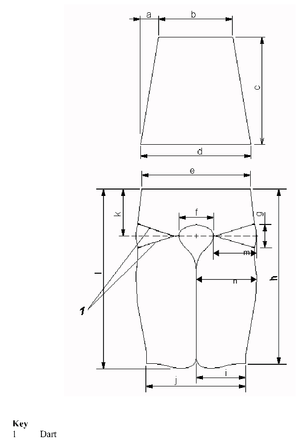
Figure A.21 – Outer cover, front and back sections
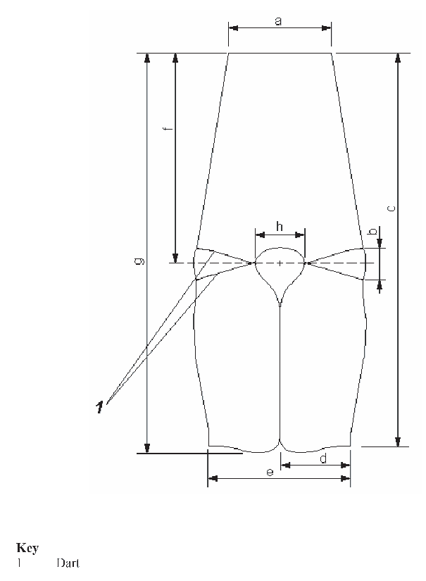
Figure A.22 – Inside cover
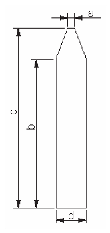
Figure A.23 – Centre gusset
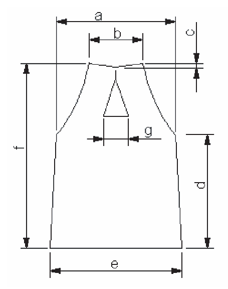
Figure A.24 – Outer and inside cover, collar
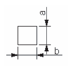
Figure A.25 – Fabric reinforcement
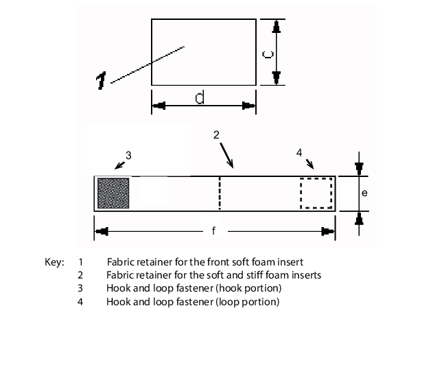
Figure A.26 – Interior foam
retainer
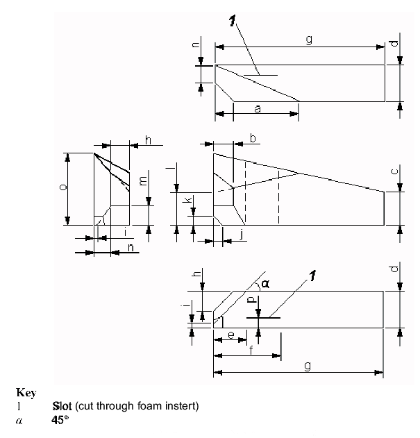
Figure A.27 – Front foam insert
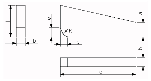
Figure A.28 – Inside front foam insert
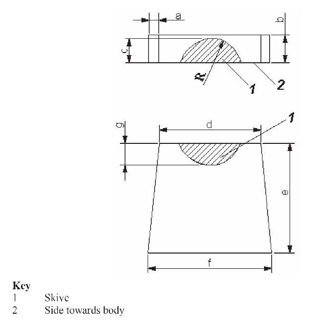
Figure A.29 – Collar foam insert
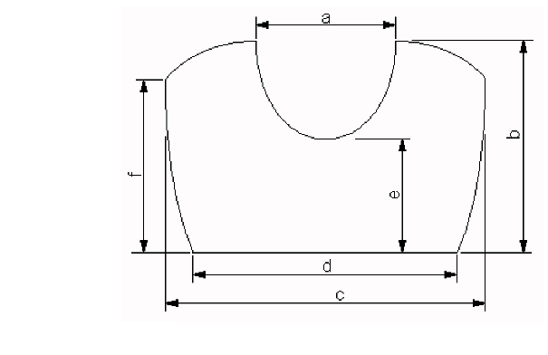
Figure A.30 – Back foam
insert

Figure A.31 – Attachments to front and back cover (dimensions on pattern,
before sewing)
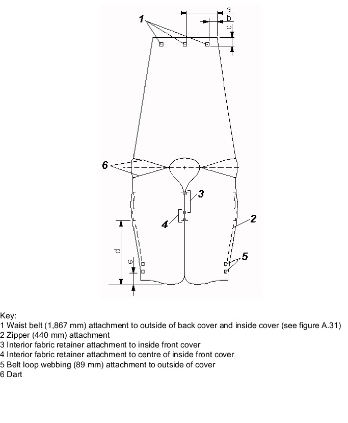
Figure A.32 – Attachments to inside cover (dimensions on pattern, before
sewing)
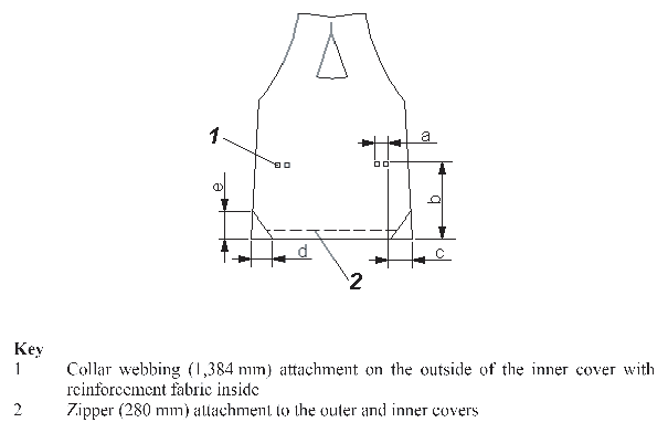
Figure A.33 – Attachments to outer and inside collar cover (dimensions on
pattern, before sewing)
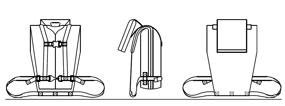
Figure A.34 – Assembly views of
finished RTD
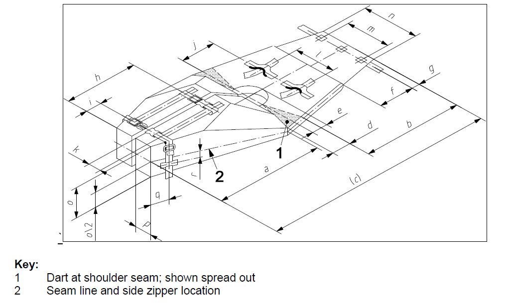
Figure A.35 – Assembly
dimensions of finished RTD body with collar removed
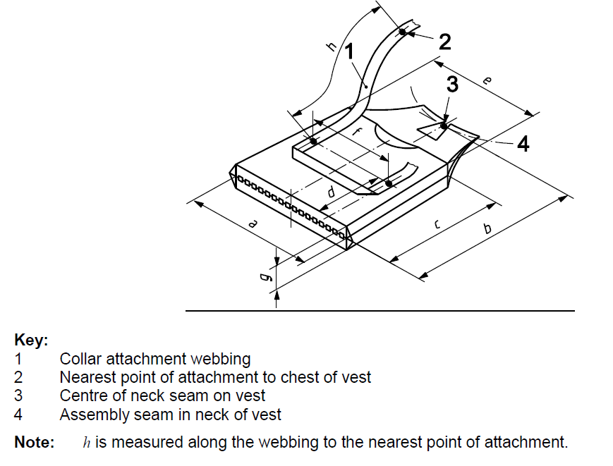
Figure A.36 – Assembly
dimensions of finished RTD collar