1 Data
1.1 General information
| Shipbuilder
|
JAPAN Shipbuilding
Company
|
| Hull no.
|
12345
|
| IMO no.
|
94111XX
|
| Ship type
|
Bulk carrier
|
1.2 Principal particulars
| Length overall
|
250.0 m
|
| Length between
perpendiculars
|
240.0 m
|
| Breadth, moulded
|
40.0 m
|
| Depth, moulded
|
20.0 m
|
| Summer load line draught,
moulded
|
14.0 m
|
| Deadweight at summer load line
draught
|
150,000 tons
|
1.3 Main engine
| Manufacturer
|
JAPAN Heavy Industries
Ltd.
|
| Type
|
6J70A
|
| Maximum continuous rating
(MCR)
|
15,000 kW x 80 rpm
|
| SFC at 75% MCR
|
165.0 g/kWh
|
| Number of sets
|
1
|
| Fuel type
|
Diesel Oil
|
1.4 Auxiliary engine
| Manufacturer
|
JAPAN Diesel Ltd.
|
| Type
|
5J-200
|
| Maximum continuous rating
(MCR)
|
600 kW x 900 rpm
|
| SFC at 50% MCR
|
220.0 g/kWh
|
| Number of sets
|
3
|
| Fuel type
|
Diesel Oil
|
1.5 Ship speed
| Ship speed in deep water at summer load line draught
at 75% of MCR
|
14.25 knots
|
2 Power curves
The power curves estimated at the design stage and modified after the
speed trials are shown in figure 2.1.
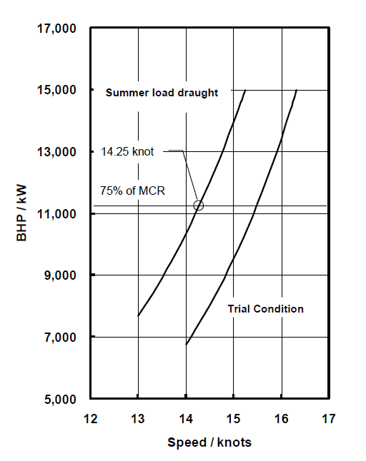
Figure 2.1: Power curves
3 Overview of propulsion system and electric power supply system
3.1 Propulsion system
3.1.2 Propeller
| Type
|
Fixed pitch propeller
|
| Diameter
|
7.0 m
|
| Number of blades
|
4
|
| Number of sets
|
1
|
3.2 Electric power supply system
3.2.1 Auxiliary engines
- Refer to paragraph 1.4 of this appendix.
3.2.2 Main generators
| Manufacturer
|
JAPAN Electric
|
| Rated output
|
560 kW (700 kVA) x 900
rpm
|
| Voltage
|
AC 450 V
|
| Number of sets
|
3
|
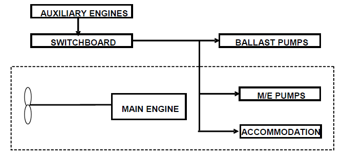
Figure 3.1: Schematic figure of propulsion and electric power
supply system
4 Estimation process of power curves at design stage
Power curves are estimated based on model test results. The flow of the estimation
process is shown below.
Figure 4.1: Flow-chart of process for estimating power curves
5 Description of energy saving equipment
5.1 Energy saving equipment the effects of which are expressed as
PAEeff(i) and/or Peff(i) in the EEDI
calculation formula
N/A
5.2 Other energy saving equipment
(Example)
5.2.1 Rudder fins
5.2.2 Propeller boss cap fins
(Specifications, schematic figures and/or photos, etc. for each piece of
equipment or device should be indicated. Alternatively, attachment of a commercial
catalogue may be acceptable.)
6 Calculated value of attained EEDI
6.1 Basic data
|
Type of ship
|
Capacity DWT
|
Speed
Vref
(knots)
|
| Bulk Carrier
|
150,000
|
14.25
|
6.2 Main engine
MCRME
(kW)
|
Shaft gen.
|
PME
(kW)
|
Type of fuel
|
CFME
|
SFCME
(g/kWh)
|
| 15,000
|
N/A
|
11,250
|
Diesel Oil
|
3.206
|
165.0
|
6.3 Auxiliary engines
| PAE
(kW)
|
Type of fuel
|
CFAE
|
SFCAE(g/kWh)
|
| 625
|
Diesel Oil
|
3.206
|
220.0
|
6.4 Ice class
N/A
6.5 Innovative electrical energy efficient technology
N/A
6.6 Innovative mechanical energy efficient technology
N/A
6.7 Cubic capacity correction factor
N/A
6.8 Calculated value of attained EEDI


attained EEDI: 2.99 g-CO2/ton mile
7 Calculated value of attained EEDIweather
7.1 Representative sea conditions
|
|
Mean
wind
speed
|
Mean
wind
direction
|
Significant
wave height
|
Mean
wave
period
|
Mean
wave
direction
|
| BF6
|
12.6 (m/s)
|
0 (deg.)*
|
3.0 (m)
|
6.7(s)
|
0 (deg.)*
|
* Heading direction of wind/wave in relation to the ship's
heading, i.e. 0 (deg.) means the ship is heading directly into the wind.
7.2 Calculated weather factor, fw
7.3 Calculated value of attained EEDIweather
attained EEDIweather: 3.32 g-CO2/ton
mile