
Section
2 Global hull loads and strength
2.1 Calculation principle
2.1.1 In each of
the global load cases for the ACV, the problem is treated as quasi-static,
where the external forces applied to the ACV at any instant are balanced
against the inertia forces produced by the acceleration of the ACV
under those external forces.
2.1.2 The weight
of the ACV is to be divided longitudinally into an appropriate number
of stations, ‘n’. The weight of the ACV may
be represented by a series of point loads distributed along the length
and the total weight is to equal the desired operational weight. The
LCG is to be determined from a weights and moments analysis.
2.1.3 The radius
of gyration in pitch, r, of the ACV is given by:
|
r
|
= |
 in metres in metres
|
|
l
m
|
= |
mass moment of inertia about the LCG, in kg/m2
|
| = |

|
2.1.4 where
|
W
i
|
= |
weight at station ‘i’ |
|
x
i
|
= |
distance of station ‘i’ from LCG |
|
W
|
= |
W
min or W
max, in kg
|
2.2 Acceleration due to wave impact
2.2.1 In theory
the ACV may receive a wave impact at any point ‘i’ along
its length, for example at the bow, stern or LCG, and the rigid body
acceleration is to be calculated for a series of impact locations
along the length to give an envelope of design values. The maximum
acceleration may not always occur at the maximum speed and/or wave
height and therefore a range of speeds and wave heights is to be investigated
to determine the design values.
2.2.2 The vertical
acceleration at the LCG, a
v,i, for the location
‘i’ to be examined for wave impact in terms of g is given
by:
|
a
v,i
|
= |
 where a
v,i is not to be taken
less than 0,5 where a
v,i is not to be taken
less than 0,5
|
where
|
K
1
|
= |
hull station load distribution factor and is to be taken as: |
|
K
1
|
= |
1,0 between stern and x
LCG
|
| = |
1,5 at bow |
intermediate values are to be determined by linear
interpolation
|
V
V
|
= |
relative vertical velocity in m/s |
|
V
v
|
= |

|
|
H
|
= |
wave
height, in metres |
|
V
|
= |
speed
of ACV at wave height H in knots
|
|
r
x
|
= |
ratio of distance measured parallel to the hull reference axis
from the LCG of the ACV to the hull longitudinal station ‘i’
at the location to be examined, to the radius of gyration in pitch
of the ACV: |
|
r
x
|
= |

|
|
d
|
= |
distance
between hull longitudinal station ‘i’ and the LCG, in
metres |
2.2.3 The acceleration, a
X,i, at any given station ‘i’ along
the hull in terms of g may then be taken as:
|
a
X,i
|
= |

|
where
d as defined in Ch 3, 2.2 Acceleration due to wave impact 2.2.2
|
l
a
|
= |
distance of point at which acceleration is required from the
LCG, in metres |
|
r
|
= |
radius
of gyration in pitch of the ACV, in metres. |
2.2.4 For a wave
impact occurring at the LCG, the vertical acceleration is constant
along the length of the ACV. Wave impacts occurring away from the
LCG will give rise to angular accelerations.
2.3 Structural response to wave impact
2.3.1 The vertical
load acting at each station as a result of the ACV acceleration is
the product of the weight, w
i, and the acceleration, a
x,i, at that station. The total vertical load acting
on the ACV is the sum of the station loads. This total vertical load
is to be balanced by the wave impact force, F
w,i,
at the chosen impact location and as given in Ch 3, 2.3 Structural response to wave impact 2.3.2. For this equilibrium condition the shear force and bending
moment distribution for the overall hull length can now be calculated.
In general, the vertical loads acting at each station and wave impact
force are to be applied as point loads and it is recommended that
the wave impact load be taken as negative. An example wave impact
force balance diagram force can be seen in Figure 3.2.1 Example wave impact force balance diagram.
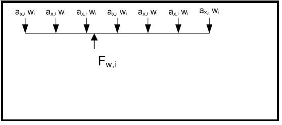
Figure 3.2.1 Example wave impact force balance diagram
2.3.3 Acceleration
due to gravity is not applied to the wave impact cases as it is assumed
that the pressure under the hull and the weight of the ACV are reasonably
uniformly distributed and will balance out.
2.4 Floating loads
2.4.1 The hogging
and sagging conditions are as illustrated in Figure 3.2.2 Sagging and Hogging Waves. A range of wave lengths and wave heights are to
be investigated to give the worst loading case and the ACV is to be
supported on a trochoidal wave(s) of all lengths that are likely to
be critical for the intended wave heights. As a minimum, hogging and
sagging wave cases are to be investigated with the trough at midship
and crests at the bow and the stern. For the purposes of this calculation
the ACV may not necessarily be immersed at all stations.
2.4.2 The wave
length to wave height ratio is to be 10:1 for wave lengths not exceeding
36,9 m. Where the wave length exceeds 36,9 m, the wave height is to
be taken as  . .
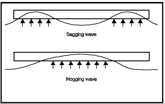
Figure 3.2.2 Sagging and Hogging Waves
2.5 Slinging and jacking loads
2.5.1 Global longitudinal
and transverse strength is to be investigated for slinging and jacking
loads. Allowance is to be made for any variation of the centre of
gravity.
2.5.2 The maximum
lifting weight and weight distribution are to be stated in the Operational
Manual.
2.6 Parking loads
2.6.1 Global longitudinal
and transverse strength is to be investigated for parking loads. The
craft is to be designed to support the maximum all-up weight on three-quarters
of the supports and other assumed worst cases depending on the positions
of the landing pads or skids.
2.7 Global strength
2.7.1 The effective
sectional area of continuous longitudinal and transverse strength
members, after deduction of openings, is to be used for the calculation
of the section modulus.
2.7.2 In general,
superstructures or deck-houses will not be accepted as contributing
to the global longitudinal or transverse strength of the ACV. However,
where it is proposed to include substantial continuous stiffening
members, special consideration will be given to their inclusion.
2.7.3 The contribution
of riveted components will be specially considered.
2.7.4 Structural
members which contribute to the overall hull girder strength are to
be carefully aligned so as to avoid discontinuities resulting in abrupt
variations of stresses and are to be kept clear of any form of opening
which may affect their structural performance.
2.7.5 For all structural
members that contribute to the hull girder strength, buckling strength
is to be adequate to withstand in-plane compressive, bending and shear
loads. Generally, the shear loads are assumed to be carried through
vertical divisions.
|
| Copyright 2022 Clasifications Register Group Limited, International Maritime Organization, International Labour Organization or Maritime
and Coastguard Agency. All rights reserved. Clasifications Register Group Limited, its affiliates and subsidiaries and their respective
officers, employees or agents are, individually and collectively, referred to in this clause as 'Clasifications Register'. Clasifications
Register assumes no responsibility and shall not be liable to any person for any loss, damage or expense caused by reliance
on the information or advice in this document or howsoever provided, unless that person has signed a contract with the relevant
Clasifications Register entity for the provision of this information or advice and in that case any responsibility or liability is
exclusively on the terms and conditions set out in that contract.
|
 |
|