
Section 1 Calculation procedure
1.1 The stress
in individual plies of a laminate is calculated in accordance with
Pt 8, Ch 3, Pt 8, Ch 3, 1 General of the Rules
and Regulations for the Classification of Special Service Craft (hereinafter
referred to as the Rules for Special Service Craft), based on bending
moment (see
Ch 3, 1 Calculation procedure 1.9) and
the laminate stiffness of a 1 cm wide elemental strip of material.
1.3 In this example
the maximum bending moment is determined from Pt 8, Ch 3, Pt 8, Ch 3, 1 General of the Rules for Special Service Craft
and occurs under the web at the base of the stiffener. It should be
noted that no reduction in the bending moment, M
b,
due to aspect ratio effect is given since the panel aspect ratio,
i.e. panel length/panel breadth is greater than 2. See Pt
8, Ch 3, Pt 8, Ch 3, 1 General of the Rules for
Special Service Craft.
1.4 The laminate
section modulus calculation is shown in Table 3.1.1 Tabulation of single skin
laminiate calculations at the end of this Section. From Figure 3.1.3 Regions of tension (T) and compression (C) in example model it will be noted that there
will be positions where tension and compression considerations will
apply. Such calculations are ideally suited to computer based investigation.
Table 3.1.1 Tabulation of single skin
laminiate calculations
|
|
Ply No.
|
Discription
|
Gc
|
Weight
|
t
|
lever @
|
E
|
E.t
|
E.t.x
|
I @
|
EI @
|
| (g/m2)
|
(mm)
|
base, x (mm)
|
(N/mm2)
|
|
|
base
|
base
|
Dry
see note
|
1
|
CSM
|
0,33
|
600
|
1,250
|
10,149
|
7200
|
9000
|
91341
|
1289,2
|
9281917
|
|
|
2
|
CSM
|
0,33
|
600
|
1,250
|
8,899
|
7200
|
9000
|
80091
|
991,5
|
7139017
|
|
|
3
|
CSM
|
0,33
|
600
|
1,250
|
7,649
|
7200
|
9000
|
68841
|
733,0
|
5277367
|
|
|
4
|
CSM
|
0,33
|
600
|
1,250
|
6,399
|
7200
|
9000
|
57591
|
513,5
|
3696967
|
|
|
5
|
WR
|
0,5
|
600
|
0,734
|
5,407
|
14000
|
10276
|
55562
|
214,9
|
3008869
|
|
|
6
|
CSM
|
0,33
|
600
|
1,250
|
4,415
|
6950
|
8688
|
38355
|
245,3
|
1704699
|
|
|
7
|
CSM
|
0,33
|
600
|
1,250
|
3,165
|
6950
|
8688
|
27496
|
126,8
|
881558
|
|
|
8
|
WR
|
0,5
|
600
|
0,734
|
2,173
|
14500
|
10643
|
23127
|
35,0
|
507333
|
|
|
9
|
CSM
|
0,33
|
600
|
1,250
|
1,181
|
6950
|
8688
|
10260
|
19,1
|
132482
|
|
|
10
|
CSM
|
0,268
|
225
|
0,556
|
0,278
|
6290
|
3497
|
972
|
0,6
|
3604
|
| Totals
|
|
|
|
|
10,774
|
|
|
86479
|
453637
|
|
31633812
|
Note 'Dry' indicates the inner surface or the hull and 'wet'
the outside of the shell laminate
|
1.5 In order to
apply a more detailed investigation it is necessary to establish the
position of the neutral axis. However, in relatively balanced laminates
this may be assumed to be at mid-depth. The procedure is simply to
carry out the calculations assuming compressive properties on one
face and tensile properties on the other face. Subsequently, the properties
should be reversed and the layer stress calculations repeated. The
calculated values should then be compared with the appropriate ultimate
properties, i.e. dependent upon whether tension or compression considerations
apply.
1.6 In the example
the moments were evaluated about the base, which was taken to be the
outer (wet) surface. The stiffness, EI, per 1 cm width,
about the neutral axis, is determined using the parallel axis theorem:
In general:
|
EI
sect
|
= |
ΣEI
base – (ΣEt)
x 10 x y
2
|
where
|
y
|
= |
distance
of neutral axis above the base (mm) |
1.7 A factor of
10 (width in mm) is introduced to correct the value of area used in
the parallel axis theorem, since a 1 cm wide strip of material is
considered in the calculations.
From the tabulation:
|
EI
sect
|
= |
31633812 – (86479 x 10 x 5,2462)
|
1.8 From Pt 8,
Ch 3, Pt 8, Ch 3, 1 General of the Rules for Special
Service Craft the individual layer stresses (tensile consideration)
are determined from:
1.9 More generally,
the calculation of the stresses in individual layers becomes:
where
|
E
i
|
= |
E
ti or E
ci for
the ply relative to its position above or below the neutral axis
|
|
y
i
|
= |
distance from the neutral axis to the outer extremity of an
individual ply, i, in mm.
|
1.10 Consider
the following typical arrangement and the associated stresses for
a single shell panel outside of the slamming zone:
Consider the outer (wet) surface:
Consider the 225g/m2 chopped strand mat reinforcement in tension:
|
σti
|
= |
693
x 10-6 x E
i
y
i
|
|
|
= |
693 x 10-6 x
6290 x 5,246
|
1.11 From Pt 8, Ch 3, Pt 8, Ch 3, 3.1 General 3.1.1 of the SSC Rules.
σult tension= 82,2 N/mm2 for CSM at G
c =0,286
Hence, stress fraction = 22,9/82,2
= 0,278.
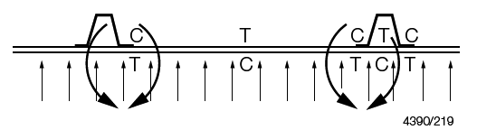
Figure 3.1.3 Regions of tension (T) and compression (C) in example model
1.12 From Table 7.3.1 Limiting stress criteria for local
loading in Pt 8, Ch 7 of the Rules
for Special Service Craft, the limiting tensile stress fraction is
0,33 for the side shell outside of the slamming zone. Hence, the calculated
stress fraction is lower than the limiting stress factor and is therefore
acceptable.
1.13 Similarly,
consider the 600g/m2 woven roving reinforcement in tension:
|
σti
|
= |
693
x 10-6 x E
i
y
i
|
|
|
= |
693 x 10-6 x
14500 x (5,246 – 0,556 – 1,25)
|
|
σult tention
|
= |
190 N/mm2 for woven roving at G
c =
0,5
|
Stress fraction = 34,6/190 = 0,182
Hence
acceptable.
1.14 Consider
the inner (dry) surface:
The 600 g/m2 chopped strand mat reinforcements at
the inner surface in compression:
|
σci
|
= |
693
x 10-6 x E
i
y
i
|
|
|
= |
693 x 10-6 x
7200 x (10,744 – 5,246)
|
|
σult comp
|
= |
122 N/mm2 for CSM at G
c =
0,33
|
Stress fraction = 27,6/122 = 0,226
Hence
acceptable.
|