
3.0 Water Mist
Nozzle Requirements
3.1 Dimensions
Nozzles should be provided with a nominal 6 mm (¼
in.) or larger nominal inlet thread or equivalent. The dimensions
of all threaded connections should conform to International Standards
where applied. National Standards may be used if International Standards
are not applicable.
3.2 Nominal Release Temperatures
[6.2]
footnote
3.2.1 The nominal release temperatures of automatic
glass bulb nozzles should be as indicated in table 1.
Table 1 Nomonal Release
Temperature
| GLASS BULB NOZZLES
|
FUSIBLE ELEMENT NOZZLES
|
| Nominal release
temp.
|
Liquid colour
code
|
Nominal release
temp.
|
Frame colour code
+
|
| 57
|
orange
|
57 to 77
|
uncoloured
|
| 68
|
red
|
80 to 107
|
white
|
| 79
|
yellow
|
121 to 149
|
blue
|
| 93–100
|
green
|
163 to 191
|
red
|
| 121–141
|
blue
|
204 to 246
|
green
|
| 163–182
|
mauve
|
260 to 343
|
orange
|
| 204–343
|
black
|
|
|
| + — Not required for decorative
nozzles.
|
3.2.2 The nominal release temperatures of fusible
automatic element nozzles should be specified in advance by the manufacturer
and verified in accordance with 3.3.
Nominal release temperatures should be within the ranges specified
in table 1.
3.2.3 The nominal release temperature that is
to be marked on the nozzle should be that determined when the nozzle
is tested in accordance with 4.6.1,
taking into account the specifications of 3.3.
3.3 Operating Temperature
(see
4.6.1
) [6.3]
Automatic nozzles should open within a temperature range
of
where X is the nominal release temperature.
3.4 Water Flow and Distribution
3.4.1 Flow Constant (see
4.10
) [6.4.1]
3.4.1.1 The flow constant K for nozzles is given
by the formula:
where
|
P |
= |
is the pressure in bars; |
|
Q |
= |
is the flow rate in litres per
minute. |
3.4.1.2 The value of the flow constant K published
in the Manufacturer's Design and Installation Instructions should
be verified using the test method of 4.10. The average flow constant K should be within ±5% of
the manufacturer's value.
3.4.2 Water Distribution (see
4.11
)
Nozzles which have complied with the requirements of the
fire test should be used to determine the effective nozzle discharge
characteristics when tested in accordance with 4.11.1. These characteristics should
be published in the Manufacturer's Design and Installation Instructions.
3.4.3 Water Droplet Size and Velocity (see
4.11.2
.)
The water droplet size distribution and droplet velocity
distribution should be determined in accordance with 8.11.2 for each
design nozzle at the minimum and maximum operating pressures, and
minimum and maximum air flow rates (when used) as part of the identification
of the discharge characteristics of the nozzles which have demonstrated
compliance with the fire test. The measurements are to be made at
two representative locations: 1) Perpendicular to the central axis
of the nozzle, exactly 1 metre below the discharge orifice or discharge
deflector, and 2) Radially outward from the first location at either
0.5 metre or 1 metre distance, depending on the distribution pattern.
3.5 Function (see
4.5
) [6.5]
3.5.1 When tested in accordance with 4.5, the nozzle should open and,
within 5 s after the release of the heat responsive element, should
operate satisfactorily by complying with the requirements of 4.10. Any lodgement of released
parts should be cleared within 60 s of release for standard response
heat responsive elements and within 10 s of release for fast and special
response heat responsive elements or the nozzle should then comply
with the requirements of 4.11.
3.5.2 The nozzle discharge components should not
sustain significant damage as a result of the functional test specified
in 4.5.6 and should have the
same flow constant range and water droplet size and velocity within
5% of values as previously determined per 3.4.1 and 3.4.3.
3.6 Strength of Body
(see
4.3
) [6.6]
The nozzle body should not show permanent elongation of
more than 0.2% between the load-bearing points after being subjected
to twice the average service load as determined using the method of
4.3.1.
3.7 Strength of Release
Element [6.7]
3.7.1 Glass Bulbs (see
4.9.1
)
The lower tolerance limit for bulb strength should be greater
than two times the upper tolerance limit for the bulb design load
based on calculations with a degree of confidence of 0.99 for 99%
of the samples as determined in 4.9.1.
Calculations will be based on the Normal or Gaussian Distribution
except where another distribution can be shown to be more applicable
due to manufacturing or design factors.
3.7.2 Fusible Elements (see
4.9.2
)
Fusible heat-responsive elements in the ordinary temperature
range should be designed to:
- sustain a load of 15 times its design load corresponding to the
maximum service load measured in 4.3.1 for
a period of 100 hours in accordance with 4.9.2.1, or
- demonstrate the ability to sustain the design load when tested
in accordance with 4.9.2.2.
3.8 Leak Resistance and
Hydrostatic Strength (see
4.4
)
[6.8]
3.8.1 A nozzle should not show any sign of leakage
when tested by the method specified in 4.4.1.
3.8.2 A nozzle should not rupture, operate or
release any parts when tested by the method specified in 4.4.2.
3.9 Heat Exposure
[6.9]
3.9.1 Glass Bulb Nozzles (see
4.7.1
)
There should be no damage to the glass bulb element when
the nozzle is tested by the method specified in 4.7.1.
3.9.2 All Uncoated Nozzles (see
4.7.2
)
Nozzles should withstand exposure to increased ambient temperature
without evidence of weakness or failure, when tested by the method
specified in 4.7.2.
3.9.3 Coated Nozzles (see
4.7.3
)
In addition to meeting the requirement of 4.7.2 in an uncoated version, coated
nozzles should withstand exposure to ambient temperatures without
evidence of weakness or failure of the coating, when tested by the
method specified in 4.7.3.
3.10 Thermal
Shock (see
4.8
) [6.10]
Glass bulb nozzles should not be damaged when tested by
the method specified in 4.8.
Proper operation is not considered as damage.
3.11 Corrosion
[6.11]
When tested in accordance with 4.12.1, all brass nozzles should
show no fractures which could affect their ability to function as
intended and satisfy other requirements.
When tested in accordance with 4.12.2, stainless steel parts of
water mist nozzles should show no fractures or breakage which could
affect their ability to function as intended and satisfy other requirements.
3.11.2 Sulphur Dioxide Corrosion (see
4.12.3
)
Nozzles should be sufficiently resistant to sulphur dioxide
saturated with water vapour when conditioned in accordance with 4.12.2. Following exposure, five
nozzles should operate when functionally tested at their minimum flowing
pressure (see 3.5.1 and 3.5.2).
The remaining five samples should meet the dynamic heating requirements
of 3.14.2.
3.11.3 Salt spray corrosion (see
4.12.4
)
Coated and uncoated nozzles should be resistant to salt
spray when conditioned in accordance with 4.12.4. Following exposure,
the samples should meet the dynamic heating requirements of 3.14.2.
3.11.4 Moist air exposure (see
4.12.5
)
Nozzles should be sufficiently resistant to moist air exposure
and should satisfy the requirements of 3.14.2 after being tested in accordance with 4.12.5.
3.12 Integrity
of nozzle coatings [6.12]
3.12.1 Evaporation of wax and bitumen used for
atmospheric protection of nozzles (see
4.13.1
)
Waxes and bitumens used for coating nozzles should not contain
volatile matter in sufficient quantities to cause shrinkage, hardening,
cracking or flaking of the applied coating. The loss in mass should
not exceed 5% of that of the original sample when tested by the method
in 4.13.1.
3.12.2 Resistance to low temperatures
(see
4.13.2
)
All coatings used for nozzles should not crack or flake
when subjected to low temperatures by the method in 4.13.2.
3.12.3 Resistance to high temperatures (see
3.9.3
)
Coated nozzles should meet the requirements of 3.9.3.
3.13 Water
hammer (see
4.15
) [6.13]
Nozzles should not leak when subjected to pressure surges
from 4 bar to four times the rated pressure for operating pressures
up to 100 bars and two times the rated pressure for pressures greater
than 100 bar. They should show no signs of mechanical damage when
tested in accordance with 4.15 and shall operate within the parametres
of 3.5.1 at the minimum design
pressure.
3.14 Dynamic
heating (see
4.6.2
) [6.14]
3.14.1 Automatic nozzles intended for installation
in other than accommodation spaces and residential areas should comply
with the requirements for RTI and C limits shown in Figure 1. Automatic nozzles intended
for installation in accommodation spaces or residential areas should
comply with fast response requirements for RTI and C limits shown
in Figure 1. Maximum and minimum RTI values for all data points calculated
using C for the fast and standard response nozzles should fall within
the appropriate category shown in Figure 1. Special response nozzles
should have an average RTI value, calculated using C, between 50 and
80 with no value less than 40 or more than 100. When tested at an
angular offset to the worst case orientation as described in section 4.6.2, the RTI should not exceed
600 (m.s.)0.5 or 250 percent of the value of RTI in the
standard orientation, whichever is less. The angular offset should
be 15° for standard response, 20° for special response and
25° for fast response.
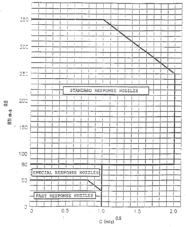
Figure 1 RTI and C Limits for Standard Orientation
3.14.2 After exposure to the corrosion test described
in sections 3.11.2, 3.11.3 and 3.11.4,
nozzles should be tested in the standard orientation as described
in section 4.6.2.1 to determine
the post exposure RTI. All post exposure RTI values should not exceed
the limits shown in Figure 1 for
the appropriate category. In addition, the average RTI value should
not exceed 130% of the pre-exposure average value. All post exposure
RTI values should be calculated as in section
4.6.2.3 using the pre-exposure conductivity factor (C).
3.15 Resistance
to heat (see
4.14
) [6.15]
Open nozzles should be sufficiently resistant to high temperatures
when tested in accordance with 4.14. After exposure, the nozzle should
not show 1) visual breakage or deformation 2) a change in flow constant
K of more than 5 percent and 3 ) no changes in the discharge characteristics
of the Water Distribution Test (see 3.4.2) exceeding 5 percent.
3.16 Resistance
to vibration (see
4.16
) [6.16]
Nozzles should be able to withstand the effects of vibration
without deterioration of their performance characteristics when tested
in accordance with 4.16.
After the vibration test of 4.16, nozzles should show no visible deterioration
and should meet the requirement of 3.5 and 3.8.
3.17 Impact
test (see
4.17
) [6.17]
Nozzles should have adequate strength to withstand impacts
associated with handling, transport and installation without deterioration
of their performance or reliability. Resistance to impact should be
determined in accordance with 4.1.
3.18 Lateral
discharge (see
4.18
) [6.19]
Nozzles should not prevent the operation of adjacent automatic
nozzles when tested in accordance with 4.2.1.
3.19 30 day
leakage resistance (see
4.19
)
[6.20]
Nozzles should not leak, sustain distortion or other mechanical
damage when subjected to twice the rated pressure for 30 days. Following
exposure, the nozzles should satisfy the test requirements of 4.22.
3.20 Vacuum
resistance (see 4.23) [6.21]
Nozzles should not exhibit distortion, mechanical damage
or leakage after being subjected to the test in 4.23.
3.21 Water
shield [6.22 and 6.23]
3.21.1 General
An automatic nozzle intended for use at intermediate levels
or beneath open grating should be provided with a water shield which
complies with 3.21.2 and 3.21.3.
3.21.2 Angle of protection (see
4.21.1
)
Water shields should provide an “angle of protection"
of 45° or less for the heat responsive element against direct
impingement of run-off water from the shield caused by discharge from
nozzles at higher elevations. Compliance with this requirement should
be determined in accordance with 4.24.1.
3.21.3 Rotation (see
4.21.2
)
Rotation of the water shield should not alter the nozzle
service load when evaluated in accordance with 4.24.2.
3.22 Clogging
(see
4.21
) [6.28.3]
A water mist nozzle should show no evidence of clogging
during 30 minutes of continuous flow at rated working pressure using
water that has been contaminated in accordance with 4.21.3. Following
the 30 minutes of flow, the water flow rated pressure of the nozzle
and strainer or filter should be within ±10 percent of the
value obtained prior to conducting the clogging test.
|
| Copyright 2022 Clasifications Register Group Limited, International Maritime Organization, International Labour Organization or Maritime
and Coastguard Agency. All rights reserved. Clasifications Register Group Limited, its affiliates and subsidiaries and their respective
officers, employees or agents are, individually and collectively, referred to in this clause as 'Clasifications Register'. Clasifications
Register assumes no responsibility and shall not be liable to any person for any loss, damage or expense caused by reliance
on the information or advice in this document or howsoever provided, unless that person has signed a contract with the relevant
Clasifications Register entity for the provision of this information or advice and in that case any responsibility or liability is
exclusively on the terms and conditions set out in that contract.
|
 |
|