
Section
6 Marine vibration excitation sources
6.1 Definition of excitation order
6.1.1 A term that is often used in relation to vibration excitations is ‘order’. First
order is invariably defined as propeller shaft frequency. For example, if operating
shaft Revolutions per minute (RPM) is 90, then first order is 90 cycles per minute
(CPM), or 1.5 cycles per second (Hz). Other orders may then be defined in relation
to this reference order. For the example of a four-bladed propeller, blade frequency
would then be 4 x 1.5 = 6 Hz, which could be termed propeller blade order, or more
specifically, fourth order.
6.2 Machinery
6.2.1 Slow Speed Diesel Main Engines
Slow speed Diesel engines are usually selected as the main engine in large cargo
ships for reasons of power and economy: however, they usually have significant
imbalances at several frequencies, and as they have to be bolted directly on to ship
structure due to their invariably large size and mass, vibration excitations can be
fully transmitted into the ship.
This type of engine is direct drive to the propeller shaft, that is, there is no
gearbox. Hence, engine crankshaft frequency and propeller shaft frequency are the
same. ‘Slow speed’ usually implies an operating RPM that is somewhere in the region
of 70 to 130 RPM.
Excitations typically include first order moments in the horizontal sense (engine
rotation about a vertical axis) and vertical sense (engine rotation about a
transverse axis), and also second order moment in the vertical sense. Sometimes, a
fourth order moment in the vertical sense may also be present.
At engine firing frequency (the order equals the number of engine cylinders for this
type of engine), invariably there is a transverse rocking moment (engine rotation
about a longitudinal axis) that is termed the ‘H-moment’. Sometimes, there can also
be a longitudinal force of significance that is generated in the crankshaft at
engine firing frequency and transmitted into the ship structure via the thrust
block.
Other slow speed Diesel engine excitations generally comprise engine twisting
moments, which are termed ‘X-moments’. These normally feature at several orders, but
because they are internal moments whereby they sum to zero in the external sense,
usually they only need to be considered if they are of large magnitude.
Because of the significant size, mass and vibration excitation characteristics of a
slow speed Diesel engine, it is recommended to include a coarse representation of
the engine in a ship finite element model; this also facilitates application of
engine excitation moments, and transverse top bracing, if fitted. Engine dimensions,
mass and vibration excitation details may be obtained from the engine builders or
the engine designers’ websites.
Figure 1.6.1 H-mode and X-mode vibration of slow speed diesel engines shows the typical vibration excitation
moments described above.
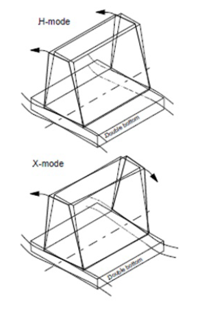
Figure 1.6.1 H-mode and X-mode vibration of slow speed diesel engines
6.2.2 Medium and High Speed Diesel Main Engines
Medium speed Diesel engines operate in the region of 500 RPM and high speed Diesel
engines in the region of 1000 RPM, through reduction gearboxes to the propeller
shaft.
They are significantly smaller and lighter than slow speed Diesel engines. Engine
manufacturers normally state for these types of engines that there is no significant
external imbalance that could affect global ship vibration, and they normally
specify resilient mounts together with suitable system connections. This should
always be arranged for passenger ships and ferries where low vibration is
required.
6.2.3 Diesel Electric and Auxiliary Machinery
Electric motors do not constitute a significant source of vibration within the
frequency range applicable to global ship vibration.
Power generation for supplying electric motors or auxiliary services is
usually provided by medium speed Diesel engines. Thereby, comments in Ch 1, 6.2 Machinery 6.2.2 apply.
6.2.4 Turbines
Steam turbines and gas turbines are in balance and do not emit vibration. If they do,
it is an indication of failure, such as a broken turbine blade.
6.2.5 Propeller Shafts
As mentioned in Ch 1, 1.1 General description of document the shafting system is subject to mandatory
classification rules, in relation to torsion, lateral and, in some cases also axial,
vibration.
Dynamic characteristics of shafting systems can affect vibration behaviour of ship
structure. Axial vibration of the shafting system can be transmitted into ship
structure via the thrust block. Torsion vibration of the shafting system would be
translated into axial vibration at the propeller, and could then also be transmitted
into the ship structure via the thrust block.
A non-uniform wake will cause fluctuating forces on a propeller which will be
transmitted to the shaft. Lateral modes of shafts may be excited by transverse and
vertical forces and moments which are developed in this way. Vibration may be
transmitted to the ship structure via the bearing housings. Avoidance of the
coincidence of a lateral mode of the shaft within 20 per cent of an excitation
source is typically required, though lateral modes may be sufficiently damped that
excessive vibration does not occur despite coincidence. The propeller blade passing
order is typically one of the more important sources of excitation for this
phenomenon.
Propulsion shafting system vibration analysis, including the engine crankshaft, is
often carried out by engine manufacturers and submitted via the Shipbuilder to
classification societies for approval. Alternatively, the calculations can be
carried out by consultants and submitted for approval, or performed by the
classification society.
In some cases therefore, it may be relevant to consider longitudinal dynamic forces
emanating from the propulsion shafting system in relation to ship vibration
analysis, which would be primarily with respect to engine firing frequency of slow
speed Diesel engines.
For certain passenger ships which have relatively stringent vibration criteria, in a
few cases, excitation from the propulsion system at first order (propeller shaft
frequency) has been noticed in measurements. In theory, this should not exist unless
there is an imbalance in the system due to a fault. Where no fault is evident, the
behaviour essentially remains unexplained. Another feature that has sometimes been
noticed during measurements for multiple screw passenger ships is gradual alteration
in phase between the propulsion systems, causing variation in measurements over
time. This ‘propeller beating’ effect can be subjectively annoying. It can often be
controlled by phase-locking the propeller shafts, preferably at the most favourable
phase relationship for minimising vibration response.
6.3 Propulsors
6.3.1 Open Propellers
Propellers gain in terms of propulsive efficiency by being located behind the ship,
in water that is moving at a velocity relative to the ship, which is lower than the
ship speed: the so-called ‘wake’. However, there is a penalty in terms of vibration,
because the water flow speed varies around the propeller disk. Hence, when the
propeller rotates, dynamic forces are generated at the propeller shaft bearings, and
through the water on to the hull surface above the propeller. Where propeller
cavitation exists, the latter effect dominates propeller excited vibration.
The degree of non-uniformity of the wake, that is, irregularity of flow into the
propeller disc, depends upon the position of the propeller and the after-body form
of the ship. For a full form ship with a single propeller, such as a typical tanker,
the wake may be quite irregular, with low velocity flow at the top of the propeller
disk, and high at the bottom: in such conditions, significant cavitation may be
generated around the top blade position. For a ship of finer form with a single
propeller, the wake would tend to be more uniform, leading to lower dynamic forces.
For twin screw ships and pod arrangements, propellers would usually be positioned in
relatively uniform flow, which is favourable from the vibration point of view.
Propeller excitation of the hull can be thought of as consisting of a non-cavitating
part, resulting from blade loading and thickness, and a cavitating part. For ships
fitted with fixed pitch propellers, the non-cavitating part will dominate at low
ship speeds where cavitation is not very pronounced. The non-cavitating pressure
excitation resembles a sine wave with the blade passing frequency. At the ship’s
normal continuous rating, hull pressure is, typically, dominated by pressure
radiated by cavitation dynamics. Cavitation is relatively repeatable per blade
passage; however, temporal variations in the inflow can produce differences in
practice.
Open propellers normally have four, five or six blades. During the design phase,
propeller dynamic forces for input to a ship vibration analysis can be obtained from
specialist calculations or model measurements. Reliable predictions from
calculations are essentially limited to blade frequency and, somewhat less
accurately, at twice the blade frequency; however, these are usually adequate to
cover the frequency range that is relevant for global ship vibration. Calculations
to predict excitation levels at higher orders are generally not reliable: these
orders can be relevant in relation to noise and vibration of local panels close to
the propeller. Model measurements can provide propeller excitation forces at blade
and at twice the blade frequencies: also at higher orders, however, these have not
always proven to be reliable.
Propeller dynamic forces at shaft bearings input to a ship vibration analysis would
typically include longitudinal force (thrust variation) at the thrust block
position, and transverse and vertical forces at the stern tube bearing position
(shaft bracket locations for a twin screw arrangement).
Hull surface forces are applied to the hull above the propeller. LR uses total
integrated hull surface force and applies it to a single substantial structural
point above the propeller. In the past, forces distributed over an area of points
above the propeller, together with phase differences between the points, were
investigated, but the increased complication was generally not justified by the
improved correlation with full-scale measurements for global ship vibration
responses.
Recommended minimum propeller clearances are stated in LR Rules and
Regulations for the Classification of Ships, Part 3, Chapter 3, 3.15.
6.3.2 Ducted Propellers
Ducted propellers can include:
- propellers in conventional positions with nozzles fitted (a common
arrangement for tugs that require high thrust at low speed);
- water jets for high speed small craft;
- azimuthing thrusters with propellers that incorporate nozzles; and
- tunnel thrusters for manoeuvring purposes (usually only in port or
restricted waters).
Generally, it is not possible to obtain reliable predictions of dynamic forces from
ducted propellers by calculation or model tests. Hence, predictive analysis is
usually confined to resonance avoidance for large deck panels local to these
devices. Thrusters can be of the ‘fixed RPM, variable pitch’ or ‘variable RPM, fixed
pitch’ types. The former type is easier to deal with from the resonance avoidance
point of view.
6.4 Sea Waves
6.4.1 Springing
Sea waves can induce ship vibration of a continuous nature, mostly at the lowest
vertical natural frequency of the hull (2-node vertical) in way of the resonance
with wave encounter frequency, which is termed ‘springing’. Generally, this is not
significant with regard to acceptable levels of ship vibration from the habitability
point of view, but may be of relevance in relation to structural fatigue for certain
types of vessel.
6.4.2 Slamming and Whipping
Slamming impacts at the ends of a ship, that depend upon hull form, draught, sea
conditions, ship speed and heading, can cause transient global vibration in the form
of whipping, as well as local response. In most cases, structural strength issues
are more relevant to consider than aspects of vibration, since comfort issues can
usually be addressed by a change of ship speed and/or heading.
|