
Section
5 Gravity base design
5.1 General
5.1.1 ISO 19901-4 Petroleum and natural gas industries – Specific
requirements for offshore structures – Part 4: Geotechnical and foundation
design considerations presents an acceptable basis of design for gravity
base foundations with ISO 19903 Petroleum and natural gas industries – Fixed
concrete offshore structures containing further guidance for large concrete
gravity base foundations. Gravity base design should consider
horizontal-moment-vertical and torsion (HMVT) loading. In addition, the following
provides further guidance on gravity base design.
5.1.2 Gravity base design requires consideration of cyclic loading effects and
the possibility of pore pressure build-up. Where a gravity base is equipped with
drainage measures, it should be ensured they will function properly throughout a
structure's life. For example, a gravel layer may be vulnerable to ingress or
migration of the underlying seabed upwards, thus reducing permeability; or drainage
channels may become blocked with fine material.
5.1.3 Gravity base design should give careful consideration to soil layering and in
particular to the presence of layers that may cause preferential sliding, or for
example other unusual soils such as peat that may affect the performance of the
foundation.
5.1.4 It is generally expected where soil conditions are complex, simplified
methodology for uniform soil conditions such as that presented in ISO 19901-4
Petroleum and natural gas industries – Specific requirements for offshore
structures – Part 4: Geotechnical and foundation design considerations can
be used to design, or size, the gravity base foundation. The preliminary analyses
should then be followed up by finite element analyses to validate the design and
take account of other factors such as more complex layering or soil stiffness
response.
5.1.5 As shown in Figure 3.5.1 Purpose and uses of skirts (exaggerated features for clarity) a gravity base may be equipped with skirts, with
possible reasons including:
- mobilising strength of deeper layers below seabed for bearing capacity;
- to improve sliding capacity by mobilising soil strength below the seabed;
- to overcome small seabed irregularities; and
- to provide some degree of scour protection; especially where skirts are
compartmentalised to prevent ingress of scour further below the
foundation.
5.1.6 Where skirts are used, it should be ensured they can penetrate the seabed and achieve
their intended purpose. Penetration may be inhibited by hazards such as boulders or
gravel layers. If full penetration is not achieved, then remedial measures, such as
under-base grouting, may be required to ensure the gravity base performance remains
satisfactory.
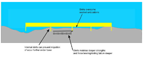
Figure 3.5.1 Purpose and uses of skirts (exaggerated features for clarity)
5.2 Sliding capacity of un-skirted gravity base on clay
5.2.1 Where a gravity base on clay seabed is not equipped with skirts the sliding capacity
needs careful consideration. Figure 3.5.2 Some issues with un-skirted foundation on clay (exaggerated features for
clarity) shows a gravity base placed onto
a clay seabed and some of the aspects that influence capacity are discussed further.
It is important that the soil characteristics immediately at the seabed (i.e. within
the top few centimetres) are characterised in terms of their capacity for sliding
resistance. Murff (2012), for example, suggests there is almost always a thin
veneer of very weak soil right at seabed. A CPT pushed from seabed is unlikely to
accurately measure the resistance in the top few centimetres of soil. It may be
possible to extract information about the top few centimetres of soil from sample
data or to use specialist equipment such as box core or t-bar if the aspect is
critical to design.
5.2.2 It is likely that there are small undulations of the seabed leading to an uneven and
reduced contact area, as shown in Figure 3.5.2 Some issues with un-skirted foundation on clay (exaggerated features for
clarity). Depending on the level of
applied load, this uneven contact area may allow drained conditions to develop. The
contact area may also depend on the applied vertical load relative to the vertical
bearing capacity and the degree of horizontal or moment loading that is applied.
High applied stress on a limited contact area of the asperities may have the effect
of increasing contact area by local failure of the soil. Uneven seabed may also have
the effect of providing drainage channels meaning that the sliding capacity on clay
may be drained or partially drained, rather than undrained.
5.2.3 In addition, the foundation itself may have holes or drainage channels. In view of
the above, consideration of an undrained case with full contact area may not be
applicable and drained loading may tend to dominate the design for sliding
resistance on clay.
5.2.4 Eurocode 7: Geotechnical design worked examples specifies a limit
of H/V < 0,4 and similarly ISO 19905-1 Petroleum and natural gas
industries -- Site-specific assessment of mobile offshore units - Part 1:
Jack-ups suggests that sliding capacity on clay should take into account an
alpha value as determined by the pile capacity method for shaft friction in clays in
the Annex A of ISO 19901-4 Petroleum and natural gas industries – Specific
requirements for offshore structures – Part 4: Geotechnical and foundation
design considerations. Neither of these criteria is particularly applicable
to the problem of sliding resistance and more detailed discussion of sliding
resistance of foundations on clay is given by Steenfelt (2017) taking into
account the drained properties of the soil with appropriate material or resistance
factors, rather than an arbitrary limit as suggested above.
5.2.5 Where sliding resistance on clay is a critical aspect then laboratory testing, field
testing and further analyses may be appropriate to enable an optimised design.
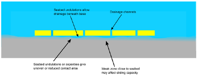
Figure 3.5.2 Some issues with un-skirted foundation on clay (exaggerated features for
clarity)
5.3 Design of gravel beds and rock berms
5.3.1 Gravel or rockfill beds are sometimes used to improve the engineering characteristics
of the seabed, often in the following ways:
- improvement of bearing capacity by spreading bearing pressure to reduce
loads on weaker layers;
- remediation of seabed features including seabed roughness or seabed slope;
- prevention of scour;
- provide drainage and prevent build-up of excess pore pressure beneath the
foundation; and
- a combination of the above factors.
5.3.2 Figure 3.5.3 Gravel bed or rock berm design issues shows some of the key engineering issues that should be considered
when designing a gravel bed. It should be noted that sliding capacity may be
affected by the pore pressure regime within the gravel bed and potential for uplift
due to hydrodynamic pressures.
5.3.3 A rock berm should be considered as an additional soil layer and should be considered
in all relevant analyses including that for capacity and stiffness.
5.3.4 A general approach for rock berm design is presented in CIRIA (2012) and
Kellezi and Stadsgaard (2012).
5.3.5 In addition to the usual requirements of a design basis, the design of the rock berm
should take account of various considerations to ensure that the central load
bearing section remains suitable for its purpose throughout the design life. These
include:
- lateral dimensions to take into account edge effects such as side slope
stability or internal stability. For gravel pads the side slope stability
may become a critical aspect. In general, the role of the side slope is to
ensure that the central crest (or plateau) of the gravel pad remains intact.
As such the slope angle should be selected such that it remains stable under
the possible load conditions including that imparted from the foundation
itself, environmental loading or other sources of loading or degradation
such as seismic;
- scour impacting stability of the gravel or rock bed;
- rock grading to ensure stability under environmental loading (i.e. wave and
current). This may also consider whether no rock loss is acceptable or some
rock loss is acceptable;
- rock grading such that it acts as a filter layer to prevent upwards
migration of the underlying soils or gradual sinking of the rock into the
seabed (Nielson et al., 2014) and to ensure sufficient permeability
of the rock to allow sufficient drainage. These two requirements sometimes
conflict each other and CIRIA (2012) contains further guidance. It
may also be necessary to use different rock grading in the rock berm to
achieve the requirements. In general, it is difficult to ensure the as
installed gravel material will satisfy a closed-filter criterion due to loss
of fines during placement. Therefore, a common approach is to use an open
filter criterion and ensure that the rock bed is thick enough to provide
sufficient drainage where required, or to demonstrate that the critical
gradient of the underlying soils will not be exceeded;
- seismic conditions and stability of the rock under seismic loading. Seismic
loading may cause degradation of underlying soil and this should be taken
into account;
- penetration of rock dump into the underlying seabed affecting the required
rock volumes;
- the rock should be competent material with good engineering properties and
this should be established during the design process and validated during
the production and installation of the rock; and
- the requirement for installation survey of rock dump and, perhaps, a
pre-installation survey where the foundation is to be installed a
significant time later. The survey should take into account the tolerances
to be achieved including overall sizing, level and surface roughness or
allowable undulations.
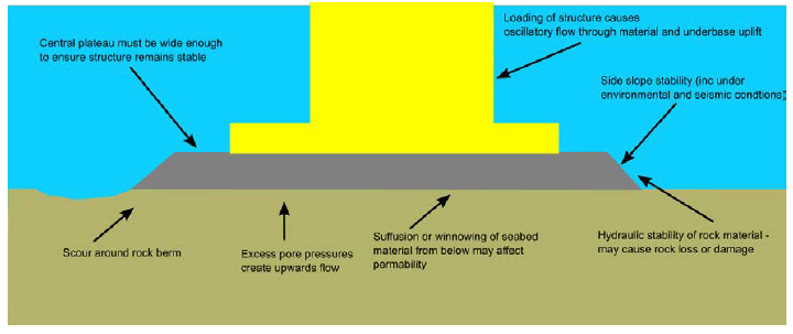
Figure 3.5.3 Gravel bed or rock berm design issues
5.4 Sliding capacity of gravity base on gravel beds and rock berms
5.4.1 A key issue when using a gravel bed is to determine the sliding friction that may be
effective between the foundation and gravel or rock. Hutchinson et al. (2010)
outline some of the key developments in international practice for the design of
breakwaters against sliding, along with some field scale testing on the impact of
base roughening on interface friction between rock and a pre-cast concrete base.
5.4.2 The interface friction between concrete and rock or gravel will depend on many
factors. This includes the relative roughness of the concrete compared to the
particle size distribution of the gravel or rock which will determine how readily
the gravel particles engage at the interface.
5.4.3 CIRIA (2012) presents a methodology based upon the residual angle of the rock
material, surface roughness, contact stress and normalised strength of the rock.
This method could be used as an initial design assumption. However, where sliding is
a critical aspect of design, and in absence of relevant testing or data already
available, it is recommended that testing is performed to justify the design
parameters used to provide an optimised design.
5.4.4 Deliberate roughening of the underside of a gravity base may be used to increase
interface friction. Deliberate roughening measures may include serrations such as
those presented by Hutchinson et al. (2010), or the use of other measures
such as studs reported by McNulty et al. (2002). In addition, or as an
alternative, ballast may be used to increase the vertical contact stress of the
foundation. McNulty et al. (2002) also discuss the placement of gravel in
mounds, rather than a continuous blanket, to ensure more even contact stress across
the whole gravity base footprint.
5.5 Sliding capacity of steel on rock
5.5.1 Where steel mudmats are required to generate sliding capacity on rock the sliding
capacity can be determined using an alpha based approach dependent on unconfined
compression strength as outlined in Ziogos et al. (2015). As described in the
paper, the roughness of the steel and basic angle of friction of the rock play an
important role in mobilisation of interface friction.
5.5.2 It should be noted that sliding capacity on rock could be adversely influenced by the
presence of a sand veneer, or mobile sand, therefore this possibility should be
considered during foundation assessment, as shown in Figure 3.5.4 Effect of mobile sand veneer on mobilisation of interface friction for
rock. It is important that the
assessment of friction takes into account the seabed conditions which are not
necessarily the same as the measured properties of the rock and steel
interfaces.
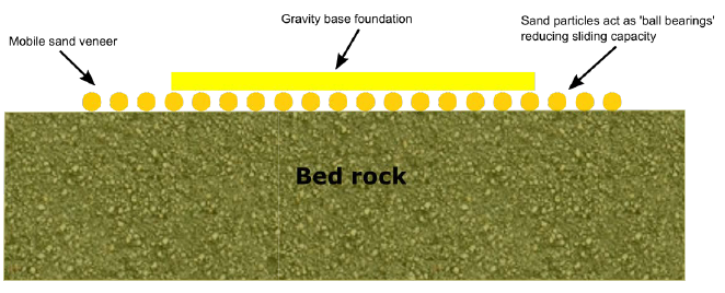
Figure 3.5.4 Effect of mobile sand veneer on mobilisation of interface friction for
rock
|
| Copyright 2022 Clasifications Register Group Limited, International Maritime Organization, International Labour Organization or Maritime
and Coastguard Agency. All rights reserved. Clasifications Register Group Limited, its affiliates and subsidiaries and their respective
officers, employees or agents are, individually and collectively, referred to in this clause as 'Clasifications Register'. Clasifications
Register assumes no responsibility and shall not be liable to any person for any loss, damage or expense caused by reliance
on the information or advice in this document or howsoever provided, unless that person has signed a contract with the relevant
Clasifications Register entity for the provision of this information or advice and in that case any responsibility or liability is
exclusively on the terms and conditions set out in that contract.
|
 |
|