
4 Strength criteria
4.1 General
The following criteria are applicable to transverse bulkheads
with vertical corrugations (see figure
2a).
Requirements for local net plate thickness are given in 4.7
In addition, the criteria given in 4.2 and 4.5 are to be complied
with.
Where the corrugation angle 4 shown in figure 2a is less than 50°,
a horizontal row of staggered shedder plates is to be fitted at approximately
mid-depth of the corrugations (see figure 2a) to help preserve
dimensional stability of the bulkhead under flooding loads. The shedder
plates are to be welded to the corrugations by double continuous welding,
but they are not to be welded to the side shell.
The thicknesses
of the lower part of corrugations considered in the application of
4.2 and 4.3 are to be maintained for a distance from the inner bottom
(if no lower stool is fitted) or the top of the lower stool not less
than 0.15.ℓ.
The thicknesses of the middle part of
corrugations considered in the application of 4.2 and 4.4 are to be
maintained to a distance from the deck (if no upper stool is fitted)
or the bottom of the upper stool not greater than 0.3.ℓ.
4.2 Bending capacity and shear stress
The bending capacity is to comply with the following relationship:
where:
|
M
|
= |
bending
moment, in kN.m, as given in 3.1
|
|
Z
le
|
= |
section modulus of one half pitch corrugation, in cm3,
at the lower end of corrugations, to be calculated according to 4.3
|
|
Z
m
|
= |
section modulus of one half pitch corrugation, in cm3,
at the mid-span of corrugations, to be calculated according to 4.4
|
|
σ
a,le
|
= |
allowable stress, in FT/mm2, as given in 4.5, for
the lower end of corrugations
|
|
σ
a,m
|
= |
allowable stress, in N/ mm2 , as given in 4.5, for
the mid-span of corrugations.
|
In no case is Z
m to be taken greater
than the lesser of 1.15.Z
le, and 1.15.Z'le for calculation of the bending capacity, Z'le being
defined below.
In case effective shedder plates are fitted
which:
- are not knuckled;
- are welded to the corrugations and the top of the lower stool
by one side penetration weld or equivalent;
- are fitted with a minimum slope of 45° and their lower edge
is in line with the stool side plating;
or effective gusset plates are fitted which:
- are fitted in line with the stool side plating;
- have material properties at least equal to those provided for
the flanges,
the section modulus Z
le, in cm3,
is to be taken not larger than the value Z'le, in cm3,
given by:
where:
|
Z
g
|
= |
section modulus of one half pitch corrugation, in cm3,
according to 4.4, in way of the upper end of shedder or gusset plates,
as applicable
|
|
Q
|
= |
shear
force, in kN, as given in 3.2
|
|
h
g
|
= |
height, in m, of shedders or gusset plates, as applicable (see figures 3a, 3b, 4a and 4b)
|
|
s
1
|
= |
as given in 2.3.1 (a)
|
|
p
g
|
= |
resultant pressure, in kN/m2, as defined in 2.5, calculated in way of the
middle of the shedders or gusset plates, as applicable
|
|
δ
a
|
= |
allowable stress, in N/mm2, as given in 4.5.
|
Shear stresses τ are obtained by dividing the shear force Q by the shear area. The shear area is to be reduced in order
to account for possible non-perpendicularity between the corrugation
webs and flanges. In general, the reduced shear area may be obtained
by multiplying the web sectional area by (sin θ), θ
being the angle between the web and the flange.
When calculating
the section moduli and the shear area, the net plate thicknesses are
to be used.
The section moduli of corrugations are to
be calculated on the basis of the requirements standards given in
4.3 and 4.4.
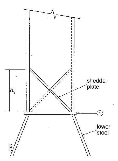
Figure 3a Symmetric shedder
plates
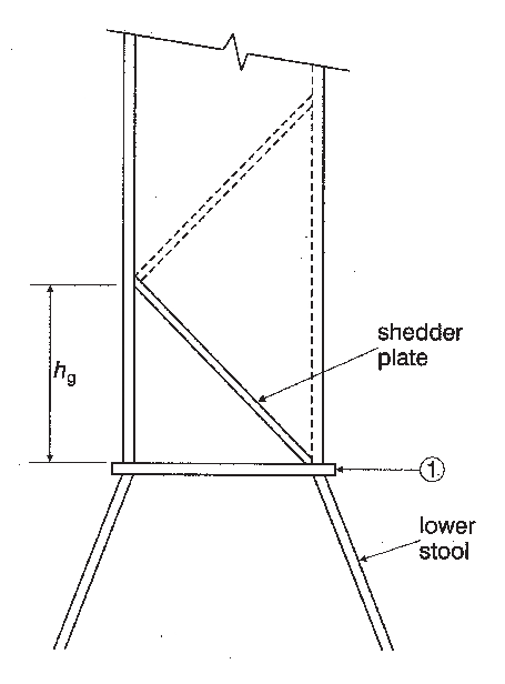
Figure 3b Asymmetric shedder
plates
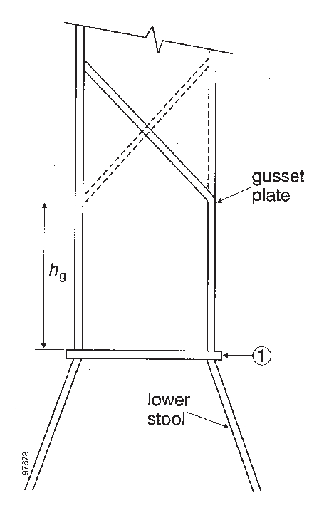
Figure 4a Symmetric
gusset/shedder plates
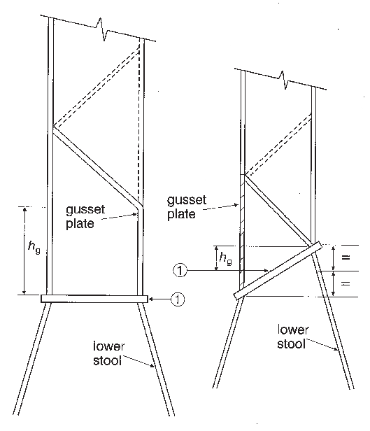
Figure 4b Asmmetric
gusset/shedder plates
Figure 5
4.3 Section modulus at the lower end of corrugations
The section modulus is to be calculated with the compression
flange having an effective flange width, b
cf,
not larger than as given in 4.6.1.
If the corrugation webs are not supported by local brackets
below the stool top (or below the inner bottom) in the lower part,
the section modulus of the corrugations is to be calculated considering
the corrugation webs 30%) effective.
-
(a) Provided that effective shedder plates, as
defined in 4.2, are fitted (see figures
3a and 3b),
when calculating the section modulus of corrugations at the lower
end (cross-section (1) in figures
3a and 3b),
the area of flange plates, in cm2, may be increased by:
- where:
|
a
|
= |
width,
in m, of the corrugation flange (see figure 2a)
|
|
t
sh
|
= |
net shedder plate thickness, in mm |
|
t
f
|
= |
net flange thickness, in mm |
|
σ
Fsh
|
= |
minimum upper yield stress, in N/mm2, of the material
used for the shedder plates
|
|
σ
Ffl
|
= |
minimum upper yield stress, in N/mm2, of the material
used for the corrugation flanges.
|
-
(b) Provided that effective gusset plates, as
defined in 4.2, are fitted (see figures 4a and 4b), when calculating
the section modulus of corrugations at the lower end (cross-section
(1) in figures 4a and 4b), the area of flange plates,
in cm2, may be increased by (7.h
g.t
gu)
- where:
|
h
g
|
= |
height of gusset plate, in m (see figures 4a and 4b), not to be taken greater
than ( .s
gu) .s
gu)
|
|
s
gu
|
= |
width of the gusset plates, in m |
|
t
gu
|
= |
net gusset plate thickness, in mm, not to be taken greater than t
f
|
|
t
f
|
= |
net flange thickness, in mm, based on the as-built condition. |
-
(c) If the corrugation webs are welded to a sloping
stool top plate which is at an angle not less than 45° with the
horizontal plane, the section modulus of the corrugations may be calculated
considering the corrugation webs fully effective. In case effective
gusset plates are fitted, when calculating the section modulus of
corrugations the area of flange plates may be increased as specified
in (b) above. No credit can be given to shedder plates only.
For angles less than 45°, the effectiveness of the web may
be obtained by linear interpolation between 30% for 0° and 100%
for 45°.
4.4 Section modulus of corrugations at cross-sections
other than the lower end
The section modulus is to be calculated with 'the corrugation
webs considered effective and the compression flange having an effective
flange width, b
cf, not larger than as given
in 4.6.1.
4.5 Allowable stress check
The normal and shear stresses σ and τ are not to exceed the allowable values σ
a and τ
a, in N/mm2, given
by:
where:
|
σ
F
|
= |
the minimum upper yield stress, in N/mm2, of the
material.
|
4.6 Effective compression flange width and shear
buckling check
4.6.1 Effective width of the compression flange
of corrugations
4.6.2 Shear
The buckling check is to be performed for the web plates
at the corrugation ends.
The shear stress τ is not to exceed the critical
value τ
c, in N/mm2, as obtained
from the following:
where:
|
τ
F
|
= |

|
|
σ
F
|
= |
minimum upper yield stress, in N/mm2, of the material
as given in 4.6.1
|
|
τ
E
|
= |

|
|
|
= |
k
t, E, t and c are given by:
|
|
k
t
|
= |
6.34 |
|
E
|
= |
modulus
of elasticity of material as given in 4.6.1 |
|
t
|
= |
net
thickness, in mm, of corrugation web |
|
c
|
= |
width,
in m, of corrugation web (see figure
2a).
|
4.7 Local net plate thickness
The bulkhead local net plate thickness t, in
mm, is given by:
where:
|
s
w
|
= |
plate width, in m, to be taken equal to the width of the corrugation
flange or web, whichever is the greater (see figure 2a)
|
|
p
|
= |
resultant
pressure, in kN/m2, as defined in 2.5, at the bottom of each strake
of plating; in all cases, the net thickness of the lowest strake is
to be determined using the resultant pressure at the top of the lower
stool, or at the inner bottom, if no lower stool is fitted or at the
top of shedders, if shedder or gusset/shedder plates are fitted.
|
|
σ
F
|
= |
minimum upper yield stress, in N/mm2, of the material.
|
For built-up corrugated bulkheads, when the thicknesses of the
flange and web are different, the net thickness of the narrower plating
is to be not less than t
n, in mm, given by:
where:
|
s
n
|
= |
the width, in m, of the narrower plating. |
The net thickness of the wider plating, in mm, is not to be
taken less than the maximum of the following values:
and
where:
|
t
np
|
= |
actual net thickness of the narrower plating and not to be greater
than 
|
|