
Section
7 Towing and lifting arrangements
7.1 Application
7.1.1 Where it is intended to transport a dock gate by means of towing or where the dock
gate will be lifted into place, the strength of fittings and supporting hull
structures are to be assessed in accordance with the requirements of this
Chapter.
7.1.2 The arrangements, equipment and fittings of sufficient safe working load are to be
provided to enable the safe conduct of all towing and lifting operations.
7.1.3 Fittings means bollards and bitts, fairleads, stand rollers, chocks used
for the towing of the dock gate, and padeyes, lifting lugs, etc. used for the
lifting of the dock gate. Any weld or bolt or equivalent device connecting the
fitting to the supporting structure is part of the shipboard fitting. Other
components such as capstans, winches, etc. are not covered by this Chapter.
7.1.4 Supporting structures means that part of the dock gate on/in which the fitting is
placed and which is directly submitted to the forces exerted on the fitting. The
supporting structure of capstans, winches, etc. used for towing operations mentioned
above is also to comply with the requirements specified in this Chapter.
7.2 Towing
7.2.1 The strength of fittings used for normal towing operations at bow, sides
and stern and their supporting hull structures are to comply with the requirements
specified in this sub-Section.
7.2.2 Fittings for towing are to be located on stiffeners and/or girders which
are part of the deck construction so as to facilitate efficient distribution of the
towing load. Other arrangements are acceptable, provided that the strength is
confirmed adequate for the intended service.
7.2.3 The design load applied to fittings and supporting hull structure is not
to be less than 1,25 times the intended maximum towing load (e.g. static bollard
pull) as indicated on the towing arrangements plan.
7.2.4 When a safe towing load TOW greater than that determined according to
Pt 2, Ch 2, 7.2 Towing 7.2.16 is requested,
then the design load is to be increased in accordance with the appropriate
TOW/design load relationship given in this Section.
7.2.5 The side projected area is to be considered for selection of towing lines
and the loads applied to fittings and supporting hull structure.
7.2.6 The increase of the minimum breaking strength for synthetic ropes need
not to be considered for the loads applied to fittings and supporting hull
structure.
7.2.7 The design load is to be applied to fittings in all directions that could
occur by considering the arrangement shown on the towing and mooring arrangements
plan. Where the towing line takes a turn at a fitting, the total design load applied
to the fitting is equal to the resultant of the design loads acting on the line,
see
Figure 2.7.1 Design load applied to
fittings.
However, in no case does the design load applied to the fitting need to be greater
than twice the design load on the line.
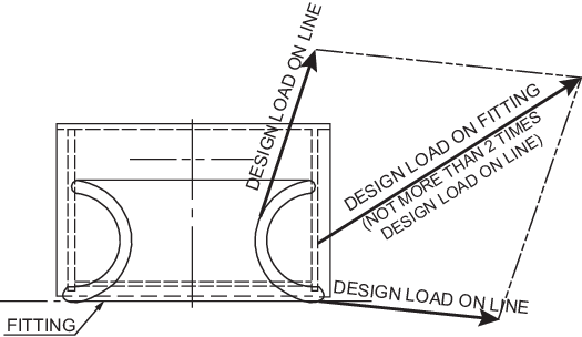
Figure 2.7.1 Design load applied to
fittings
7.2.8 Fittings are to be selected from an acceptable National or International
standard and to be based on the intended maximum towing load (e.g. static bollard
pull) as indicated on the towing arrangements plan.
7.2.9 Towing bitts (double bollards) are to be chosen for the towing line
attached with an eye splice if the industry standard distinguishes between different
methods to attach the line, i.e. figure of eight or eye splice attachment.
7.2.10 When the fitting is not selected from an accepted industry standard, the
strength of the fitting based on net scantlings and its attachment to the dock gate
is to be adequate for the loads specified in Pt 2, Ch 2, 7.2 Towing 7.2.3 based on the
acceptance criteria given in Pt 2, Ch 2, 7.2 Towing 7.2.10 or Pt 2, Ch 2, 7.2 Towing 7.2.11 as appropriate.
Towing bitts (double bollards) are required to resist the loads caused by the towing
line attached with an eye splice. For strength assessment, beam theory or finite
element analysis using net scantlings is to be applied, as appropriate. Corrosion
additions and wear down allowance is to be added to the net scantlings as defined in
Pt 2, Ch 2, 7.2 Towing 7.2.13 and Pt 2, Ch 2, 7.2 Towing 7.2.15.
7.2.11 The net scantlings of the supporting structure for the fittings are to
be adequate for the loads specified in Pt 2, Ch 2, 7.2 Towing 7.2.3 based on the
acceptance criteria given in Pt 2, Ch 2, 7.2 Towing 7.2.11 or Pt 2, Ch 2, 7.2 Towing 7.2.12 as appropriate.
The reinforced members beneath fittings are to be effectively arranged for any
variation of direction (horizontally and vertically) of the towing forces acting
upon the fittings, see
Figure 2.7.2 Supporting hull
structure for a sample
arrangement. Proper alignment of the fitting and its supporting hull structure is to
be ensured. The acting point of the towing force on a fitting is to be taken at the
attachment point of a towing line or at a change in its direction. For bollards and
bitts, the attachment point of the towing line is to be taken not less than 4/5 of
the tube height above the base as indicated in Figure 2.7.2 Supporting hull
structure. Corrosion
additions and wear down allowance is to be added to the net scantlings as defined in
Pt 2, Ch 2, 7.2 Towing 7.2.13 and Pt 2, Ch 2, 7.2 Towing 7.2.15.
7.2.13 For strength calculations by means of finite element analysis, the
geometry is to be idealised as realistically as possible. The ratio of element
length to width is not to exceed 3. Girders are to be modelled using shell or plane
stress elements. Symmetric girder flanges are generally to be modelled by beam or
truss elements. At least three elements are to be used across the depth of the
girder. In way of small openings in girder webs the web thickness is to be reduced
to a mean thickness over the web height. Large openings are to be modelled.
Stiffeners are generally to be modelled by using shell, plane stress, or beam
elements. Stresses are to be read from the centre of the individual element. For
shell elements the stresses are to be evaluated at the mid-plane of the element. The
equivalent stress within the supporting structure of fittings is not to exceed the
specified minimum yield strength of the material.
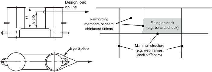
Figure 2.7.2 Supporting hull
structure
7.2.14 An allowance for corrosion is to be added to the net thickness derived
as indicated below:
- For the supporting structure, a corrosion addition of 2 mm is to
be added to the net thickness derived.
- For pedestals and foundations on deck which are not part of a
fitting according to an accepted industry standard, 2,0 mm.
- For shipboard fittings not selected from an accepted industry
standard, 2,0 mm.
Table 2.7.1 Allowable stress within
the supporting structure of fittings
|
|
Normal stress, in
N/mm2
|
Shear stress, in
N/mm2
|
| Allowable stress
|

|

|
| where

σo = specified minimum yield strength of the
material in N/mm2
Note Normal stress
is defined as the sum of bending and axial stresses. No
stress concentration factors are accounted for and as such
may need to be considered separately.
|
7.2.15 In addition to the corrosion addition given in Pt 2, Ch 2, 7.2 Towing 7.2.13, the wear
allowance, tw, for fittings that are not selected from an
acceptable National or International Standard, is not to be less than 1,0 mm, added
to surfaces which are intended to regularly contact the line.
7.2.16 The safe towing load (TOW) is the load limit for towing purposes. TOW
used is not to exceed 80 per cent of the design load specified by Pt 2, Ch 2, 7.2 Towing 7.2.3.
7.2.17 TOW, in tonnes, of each fitting is to be marked (by weld bead or
equivalent) on the deck fittings used for towing.
7.2.18 The above requirements on TOW apply for the use with no more than one
towline. If not otherwise chosen, for towing bitts (double bollards) TOW is the load
limit for a towing line attached with an eye-splice.
7.3 Lifting
7.3.1 The strength of fittings used to lift a dock gate in and out of water and
their supporting hull structures are to comply with the requirements of this
sub-Section.
7.3.2 Padeyes and lifting lugs are to be located on stiffeners and/or girders which are
part of the deck construction so as to facilitate efficient distribution of the
lifting load. Other arrangements are acceptable, provided that the strength is
confirmed adequate for the intended service.
7.3.3 The provision of padeyes is to be such that a uniform lift is achieved with no
off-centre loading of the lifting appliance occurring.
7.3.4 The design of padeyes is to be in accordance with a recognised national or
international standard.
7.3.5 The padeye can be manufactured from one single plate, have a cheek plate
fillet welded on each side of the plate or have a boss which is fillet welded
through the plate, see
Figure 2.7.3 Acceptable padeye
design. Padeyes
where the boss is only partly welded to the plate are not permitted.
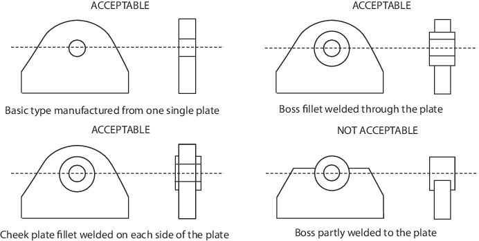
Figure 2.7.3 Acceptable padeye
design
7.3.6 All padeyes and lifting lugs are to be marked with their specific SWL. The locations
and SWL of the padeyes and lifting lugs is to be recorded on the towing and lifting
arrangement plan.
7.3.7 All padeyes and lifting lugs are to be tested to 1,5 times the SWL, as a vertical
load only.
7.3.8 The net scantlings of supporting structures are to be assessed in
accordance with Pt 2, Ch 2, 7.2 Towing 7.2.9 to Pt 2, Ch 2, 7.2 Towing 7.2.12 where the design
load is to be taken as the SWL of the padeye and the acceptance criteria are given
in Table 2.7.2 Allowable stress within
the supporting structure of padeyes. The reinforced members beneath the
padeye are to be effectively arranged for any variation of direction (horizontally
and vertically) of the lifting forces acting upon the padeye. Corrosion additions
and wear down allowance is to be added to the net scantlings as defined in Pt 2, Ch 2, 7.2 Towing 7.2.13.
Table 2.7.2 Allowable stress within
the supporting structure of padeyes
|
|
Normal stress, in
N/mm2
|
Shear stress, in
N/mm2
|
| Allowable stress
|

|

|
| where

σo = specified minimum yield strength of the
material in N/mm2
Note Normal stress
is defined as the sum of bending and axial stresses. No
stress concentration factors are accounted for and as such
may need to be considered separately.
|
7.3.9 The global strength of the dock gate (longitudinal and transverse)
during lifting operations is to be assessed taking into account the hoisting speed
of the lifting appliance, the stiffness of the wires, the residual weights, liquids,
etc, on the pontoon and the distribution of the padeyes.
7.4 Towing and lifting arrangements plan
7.4.1 The SWL and TOW for the intended use for each shipboard fitting is to be noted in the
towing and lifting arrangements plan which is to be made available for towing and
lifting operations. It is to be noted that TOW is the load limit for towing purposes
and SWL that for lifting purposes.
7.4.2 Information provided on the plan is to include in respect for each shipboard fitting:
- location on the pontoon;
- fitting type;
- SWL/TOW;
- manner of applying towing line load, including limiting
fleet angles; and
- manner of applying lifting load, including limiting
angles.
Note that item (c) is subject to approval. Fleet angle is defined as the maximum
angle the line deviates from a direction perpendicular to the drum axis of a towing
winch. The limiting angles for the purposes of lifting are defined as the maximum
angles assumed in the derivation of the SWL for each padeye.
|