
Section
2 Rudders
2.1 General
2.1.1 Requirements
are given in this Section for double and single plate rudders and
also for certain types of higher efficiency rudders.
2.1.2 The scantlings
of flanking rudders (rudders fitted forward of the propeller to improve
steering when navigating astern) are to be in accordance with the
requirements for rudders fitted abaft the propeller. However, the
scantlings are to be not less than required for an astern speed equal
to the normal service speed ahead. This type of rudder is to be provided
with stops at a maximum angle of helm of 45°.
2.1.3 The scantlings
of a bow rudder are to be in accordance with the requirements for
rudders out of the propeller slip stream applying the maximum speed,
ahead or astern, at which the rudder will be used or half the service
speed, whichever is the greater. Efficient arrangements are to be
provided for locking the rudder in the centreline position when not
in use, see
Pt 5, Ch 15, 1.6 Rudder, rudder stock, tiller and quadrant 1.6.4.
2.1.4 Rudder
systems of special design will be considered on the basis of these
Rules and full details on the loadings of these rudders are to be
given; model tests may be required to support the calculations.
2.1.5 Rudders
are to be efficiently supported in the ship’s structure by means
of suitable carriers in the steering gear flat, or in the solepiece
gudgeons. Where the weight of the rudder is supported by carrier bearings
the structure in way is to be adequately strengthened and the deck
plating increased in thickness.
2.1.6 Rudder
stocks are to be enclosed by watertight trunks or tubes which are
to be fitted with an efficient watertight gland or other approved
type of seal when the top of the trunks (steering gear flat) is less
than 300 mm above the deepest waterline in any trimmed condition.
2.1.7 Arrangements
to prevent the rudders from lifting are to be fitted. Their strength
and that of the supporting structure is to be such that damage to
the steering gear in case of touching bottom is prevented, see
Pt 5, Ch 15, 2.1 General 2.1.2.(b).
2.2 Rudder stock and bearings
2.2.1 The scantlings
of the rudder stock are to be not less than required by Table 12.2.1 Rudder stock diameter.
Table 12.2.1 Rudder stock diameter
| Item
|
Requirement
|
|
(1) Basic stock diameter, δS, at and below lowest
bearing for mild steel
|
 mm mm
|
| (2) Stock diameter, δSO,
corrected for higher tensile steel
|

|
|
(3) Diameter in way of tiller, δSU
|
|
δsu |
= |
δSO in (1) with N = 0 |
For spade rudders:
δSU ≥ 0,7δS
|
| Symbols
|
|
For σo > 235 (24) = (235/σo)0,75
(24/σo)0,75
For σo ≤ 235 (24) = (235/σo) (24/σo)
|
PL |
= |
lateral force on rudder acting at centre of pressure blade |
| = |
117,5KRf(V +
5.6)2AR |
|
|
NOTE
Where the astern speed is expected to be more than 0,5 × the
speed ahead, δS will be specially considered.
σo is to be taken not greater than 70 per cent of
the ultimate tensile strength or
450 N/mm2 (45,9 kgf/mm2), whichever is
the lesser, so is not to be less than
200 N/mm2, see
Ch 5, 2.4 Mechanical tests 2.4.6 of the
Rules for the Manufacture, Testing and Certification of Materials, July 2022
.
|
Table 12.2.2 Rudder coefficient k
R
| Design
criteria
|
k
R
|
| Rudder in propeller slipstream
|
0,248
|
| Rudder out of propeller
slipstream
|
0,235
|
| Barge – non-self-propelled
|
0,226
|
| Symbols
|
|
|
Table 12.2.3 Position of centre of
pressure
| Design
criteria
|
Value of x
P to be used in Table 12.2.1 Rudder stock diameter
|
| Rectangular rudders
|
but not less than 0,12x
B
|
| Non-rectangular rudders
|
x
P as calculated from geometric form (see Note)
but not less than 
|
| Symbols
|
|
x
B
|
= |
breadth of rudder, in metres |
|
x
L
|
= |
horizontal distance from leading edge of the rudder,
to the pintles, or axle, in metres |
|
x
P
|
= |
horizontal distance from the centreline of the rudder
pintles, or axle, to the centre of pressure, in metres |
|
x
S
|
= |
horizontal length of any rectangular strip of rudder
geometric form, in metres |
|
y
R
|
= |
depth of rudder on centreline of stock, in
metres |
|
|
NOTE
For rectangular strips the centre of pressure should be
assumed to be located 0,33x
S abaft leading edge of strip.
|
Table 12.2.4 Pintle arrangement coefficient,
N
see Fig. 12.2.1
Table 12.2.5 Rudder coefficient f
| Rudder angle
|
2 × 35°
|
2 × 45°
|
2 × 55°
|
Rudder
profile
Type 1
|
1,0
|
1,23
|
1,43
|
Rudder profile
Type 2
|
1,60
|
1,97
|
-
|
Rudder profile
Type 3
|
1,15
|
1,42
|
1,64
|
| Symbols
|
| Rudder
profile Types 1, 2, and 3, see
Figure 12.2.3 Rudder profile types
|

Figure 12.2.1 Pintle arrangements
2.2.2 For rudders
having an increased diameter of the rudder stock in way of the rudder, see
Figure 12.2.2 Taper of rudder stock, the
increased diameter is to be maintained to a point as far as practicable
above the top of the lowest bearing. This diameter may then be tapered
to the diameter required in way of the upper bearing and further to
the diameter at tiller. The length of the taper is to be at least
three times the reduction in diameter. Particular care is to be taken
to avoid the formation of a notch at the upper end of the taper. The
design of the upper part of the rudder stock and of the upper rudder
stock bearing is to take account of any forces which may be imposed
by the steering engine, especially in the case where two or more rudders
are activated by one steering engine.
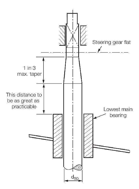
Figure 12.2.2 Taper of rudder stock

Figure 12.2.3 Rudder profile types
2.2.3 Sudden
changes of section or sharp corners in way of the rudder coupling,
and shoulders for rudder carriers are to be avoided. Jumping collars
are not to be welded to the rudder stock. Keyways in the rudder stock
are to have rounded ends and the corners at the base of the keyway
are to be radiused.
2.2.4 The design
of the lowest bearing is to comply with the requirements of Table 12.2.6 Lowest main bearing
requirements.
Table 12.2.6 Lowest main bearing
requirements
| Item
|
Requirements
|
| Lowest
main bearing
|
Depth zB, in mm
|
| 1,5δSO ≥ z
B ≥ 1,0δSO
|
| For
spade rudders:
|
| 1,5δSO ≥ z
B ≥ 1,3δSO
|
| Bearing pressure (on the
projected area of the lowest main bearing), where the area is to be taken as
the projected length × diameter
|
Bearing
material
|
Maximum pressure, in N/mm2
(kgf/cm2)
|
| Metal
|
6,87 (70,0)
|
| Synthetic
|
4,41 (45,0)
|
| Lignum Vitae
|
2,45 (25,0)
|
| Clearance in lowest main
bearing on the diameter (note should be taken of the manufacturer's
recommended clearances, particularly where bush material requires
pre-soaking)
|
Bearing
material
|
Clearance, in mm
|
| Metal (see note)
|
0,001δSO + 1,0
|
| Synthetic
|
0,002δSO + 1,0
but not less than 1,5
|
| Symbols
|
|
z
B
|
= |
depth of lowest bearing, in mm |
|
|
NOTE
For bearings which are pressure lubricated the clearance
must be restricted to enable the pressure to be maintained.
|
2.2.5 Where
liners are fitted to rudder stocks or pintles, they are to be shrunk
on or otherwise efficiently secured. If liners are to be shrunk on,
the shrinkage allowance is to be indicated on the plans. Where liners
are formed by stainless steel weld deposit, the stocks and pintles
are to be of weldable quality steel, and details of the procedure
are to be submitted, see also
Pt 3, Ch 12, 2.2 Rudder stock and bearings 2.2.6.
2.2.6 Where
it is proposed to use stainless steel liners and bushes for rudder
stock and/or pintle bearings, the chemical composition and mechanical
properties are to be submitted for approval. Materials for bushes
and liners are to have a suitable difference in hardness. Synthetic
rudder bearing materials are to be of a type approved by Lloyd’s
Register (hereinafter referred to as LR).
2.3 Rudder construction – Doubled plated
2.3.1 The scantlings
of a double plated rudder are to comply with Table 12.2.7 Double plated rudder
construction, but the thickness of
the rudder plating may require to be increased in way of the rudder
coupling and the heel pintle.
Table 12.2.7 Double plated rudder
construction
| Item
|
Requirements
|
|
(1) Side plating
|
|
t
|
= |
3yW (1,45 + 0,1  ) + 2 mm ) + 2 mm |
|
|
(2) Webs - vertical and horizontal
|
As (1) above
|
|
(3) Top and bottom plates
|
As (1) above using y
W = maximum rudder width, in metres, at top or bottom, but not
less than 0,9 m
|
|
(4) Nose plates
|
tN ≥ 1,25t from (1)
|
|
(5) Mainpiece - fabricated
|
Breadth and width ≥ δSO
|
tM
|
= |
5 + 0,56 mm mm |
|
|
rectangular, see Note
|
Minimum fore and aft extent of side
plating = 0,2x
B
|
| Stress due to bending ≤ 5,0
kgf/mm2
|
|
(6) Mainpiece - tubular, see Note
|
Inside diameter ≥ δSO
tM as for (5)
Side plating as for (1)
Bending stress as for (5)
|
| Symbols
|
|
tM
|
= |
thickness of side plating and vertical webs forming
mainpiece or of tube, in mm |
|
tN
|
= |
thickness of nose plate, in mm |
|
yW
|
= |
vertical spacing, in metres, of the horizontal webs,
but is not to exceed 0,9 m |
|
xB
|
= |
breadth of rudder on centreline of stock, in
metres |
|
|
|
2.3.2 Adequate
hand or access holes are to be arranged in the rudder plating in way
of the pintles as required and the rudder plating is to be reinforced
locally in way of these openings. Continuity of the modulus of the
rudder mainpiece is to be maintained in way of the openings.
2.3.4 Connection
of rudder side plating to vertical and horizontal webs, where internal
access for welding is not practicable, is to be by means of slot welds
on to flat bars on the webs. The slots are to have a minimum length
of 75 mm and in general, a minimum width of twice the side plating
thickness or 20 mm whichever is the greater. The ends of the slots
are to be rounded. The space between the slots is not to exceed 150
mm. Alternatively the side plating may be fitted in panels, fillet
welded all round either directly on to webs of increased thickness
or on to flat bars on the webs.
2.3.5 Double
plate rudders are to be efficiently coated internally and means for
draining the rudder are to be provided in way of the lowest part of
the rudder when the rudder is mounted in its normal position.
2.3.7 Where
the fabricated mainpiece of a spade rudder is connected to the horizontal
coupling flange by welding, a full penetration weld is required.
2.4 Rudder construction – Single plated
2.4.1 The scantlings
of a single plated rudder are to be not less than required by Table 12.2.8 Single plate rudder
construction.
Table 12.2.8 Single plate rudder
construction
| Item and
parameter
|
Requirements
|
| Blade thickness
|
The greater of:
|
t
|
= |
5 + 0,02δSO + 10yW mm |
|
|
|
| Section modulus of arms
|
|
Z
|
= |
0,25 × y
W
2 × x
W(V + 5,6)2 cm3
|
|
| Diameter of mainpiece
|
Diameter = δSO mm,
see Note to Table 12.2.7 Double plated rudder
construction
|
| Symbols
|
|
xW
|
= |
breadth of rudder blade aft of stock, in metres |
|
yW
|
= |
vertical spacing, in metres, of the arms, but is not
to exceed 0,9 m |
|
V
|
= |
ship’s speed, in km/h |
|
Z
|
= |
section modulus, in cm3
|
|
2.4.3 Rudder
arms are to be efficiently attached to the mainpiece.
2.5 Rudder couplings
2.5.1 Rudder
coupling design is to be in accordance with Table 12.2.9 Rudder couplings to stock. Conical couplings will
be specially considered.
Table 12.2.9 Rudder couplings to stock
| Arrangement
|
Parameter
|
Requirements
|
| Horizontal
coupling
|
Vertical
coupling
|
| Bolted couplings
|
n
|
≥ 6
|
≥ 8
|
| δb
|
|
|
|
m
|
0,00071nδS δb
2 δb
2
|
0,00043  δS
3 δS
3
|
|
t
f
|
≥ δb
(see Note 1)
|
δb
|
αmax
(see Note 2)
|
|
-
|
αas built
(see Note 2)
|
≤ αmax
|
-
|
|
w
f
|
0,67δb
|
0,67δb
|
| Symbols
|
|
k1
|
= |
the greater of k
s and k
f
|
|
kf
|
= |
upper coupling flange material factor |
|
ks
|
= |
rudder stock material factor |
|
m
|
= |
first moment of area of bolts about centre of
coupling, in cm3
|
|
n
|
= |
number of bolts in coupling |
|
tf
|
= |
minimum thickness of coupling flange, in mm |
|
tfa
|
= |
as built flange thickness, in mm |
|
w
f
|
= |
width of flange material outside the bolt holes, in
mm |
|
R
|
= |
palm radius between rudder stock and connected
flange, not smaller than  , in mm , in mm |
|
|
αas built
|
= |
stress concentration factor for as built
scantlings |
| = |

|
|
αmax
|
= |
maximum allowable stress concentration factor |
|
δb
|
= |
diameter of coupling bolts, in mm |
|
PL
|
= |
lateral force acting on the rudder, in N, is to be
calculated for both ahead and astern conditions. The greater of the
two values is to be used |
|
MT |
= |
maximum turning moment applied to stock, and is take to be as the
greates of:
 - The torque generated by the steering gear att he maximum
working pressure (see
Pt 5, Ch 15, 1.2 Definitions 1.2.8 )
|
|
V
|
= |
maximum service speed with the ship in the loaded
condition, in km/h |
|
|
Note
1. For spade rudders with horizontal
coupling, t
f is not to be less than 0,25δSO.
|
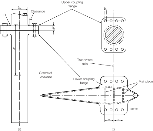
Figure 12.2.4 Rudder stock connection
2.5.2 For rudders
with horizontal coupling arrangements, where the upper flange is welded
to the rudder stock, a full penetration weld is required and its integrity
is to be confirmed by non-destructive examination. Such rudder stocks
are to be subjected to a furnace post-weld heat treatment (PWHT) after
completion of all welding operations. For carbon or carbon manganese
steels, the PWHT temperature is to be not less than 600°C.
2.5.3 The connecting bolts for coupling the rudder to the rudder stock are to be
positioned with sufficient clearance to allow the fitting and removal of the bolts and
nuts without contacting the palm radius, R, see
Pt 3, Ch 12, 2.5 Rudder couplings 2.5.1. The surface forming the palm radius is to
be free of hard and sharp corners and is to be machined smooth to the Surveyor’s
satisfaction. The surface in way of bolts and nuts is to be machined smooth and to the
Surveyor’s satisfaction.
2.5.4 For spade rudders fitted with a fabricated rectangular mainpiece, the
mainpiece is to be designed with its forward and aft transverse sections at equal
distances forward and aft of the rudder stock transverse axis, see
Pt 3, Ch 12, 2.5 Rudder couplings 2.5.1.
2.6 Pintles
2.6.2 When coned
pintles are fitted special attention is to be paid to the fit of the
pintle taper into its housing. The pintle taper is not to exceed one
in six on the diameter, but to facilitate removal of the pintles it
is recommended that the taper be not less than 1 in 12 on the diameter.
Table 12.2.10 Pintle requirements
| Item
|
Requirements
|
|
(1) Pintle diameter (measured outside liner if fitted)
|
|
δPL
|
= |

|
where for single pintle rudders:
|
A
PL
|
= |

|
and for rudders with two or more pintles:
|
A
PL
|
= |

|
|
|
(2) Bearing length
|
z
PB ≥ 1,2δPL
|
|
(3) Gudgeon thickness in way of pintle (measured outside bush
if fitted)
|
b
G ≥ 0,5δPL
|
|
(4) Recommended pintle clearance (note should be taken of the
manufacturer's recommended clearances, particularly where bush material
requires pre-soaking)
|
Bearing
material
|
Clearance, in
mm
(on diameter)
|
| Metal
|
0,001δPL + 1,0
|
| Synthetic
|
0,002δPL + 1,0
but not less than 1,5
|
| Symbols
|
|
b
G
|
= |
thickness of gudgeon material in way of pintle, in
mm |
|
z
PB
|
= |
pintle bearing length, in mm |
|
A
PL
|
= |
rudder area supported by the pintle, in m2
|
|
N
PL
|
= |
number of pintles on the rudder |
|
V
|
= |
ship speed, in km/h, but not less than 12 km/h |
|
δPL
|
= |
pintle diameter, in mm |
|
Note Proposals for higher pressures or other materials will be
specially considered on the basis of satisfactory test results.
|
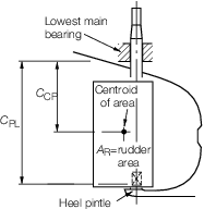
Figure 12.2.5 Dimensions for pintle requirements
|