
Section
3 Structural idealisation
3.1 General
3.1.1 For derivation
of scantlings of stiffeners, beams, girders, etc. the formulae in
the Rules are normally based on elastic or plastic theory using simple
beam models supported at one or more points and with varying degrees
of fixity at the ends, associated with an appropriate concentrated
or distributed load.
3.1.3 For flat
bar stiffeners, the ratio of depth to thickness should not exceed
16.
3.2 Geometric properties of section
3.2.1 The symbols
used in this sub-Section are defined as follows:
|
t
p
|
= |
the thickness, in mm, of the attached plating. Where this varies,
the mean thickness over the appropriate span is to be used |
|
f
|
= |
 but is not to exceed 1,0. but is not to exceed 1,0. |
Values of this factor are given in Table 3.3.2 Values of f as a function
of l/b .
Table 3.3.2 Values of f as a function
of l/b
|
|
f
|
|
f
|
| 0,5
|
0,19
|
3,5
|
0,69
|
| 1,0
|
0,30
|
4,0
|
0,76
|
| 1,5
|
0,39
|
4,5
|
0,82
|
| 2,0
|
0,48
|
5,0
|
0,88
|
| 2,5
|
0,55
|
5,5
|
0,94
|
| 3,0
|
0,62
|
6 and above
|
1,00
|
Note Intermediate values to be obtained by linear
interpolation.
|
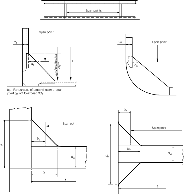
Figure 3.3.1 Determination of span points
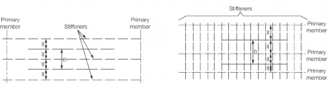
Figure 3.3.2 Determination of load-bearing plating
3.2.2 The effective
geometric properties of rolled or built sections may be calculated
directly from the dimensions of the section and associated effective
area of attached plating. Alternatively, the geometric properties
may be taken from Pt 3, Ch 3, 5 Geometric properties of rolled sections. Where
the web of the section is not normal to the attached plating, the
angle is not normal to the attached plating, and exceeds 20, the properties
of the section are to be determined about an axis parallel to the
attached plating, alternatively, the required section modulus is to
be multiplied by a factor:
α is the angle between stiffener and plating.
3.2.3 The geometric
properties of rolled or built stiffener sections are to be calculated
in association with an effective area of attached load-bearing plating
of thickness t
p in mm and of width 500 mm;
for swedges, the width of plating is to be taken as the actual width
of flat plating between the swedges. The thickness, t
p,
is the actual thickness of the attached plating. Where this varies,
the mean thickness over the appropriate span is to be used.
3.2.4 The effective
section modulus of a corrugation over a spacing, s, is
to be calculated from the dimensions, and for symmetrical corrugations,
may be taken as:
where d
w, b, t
p, c and t
w are
measured, in mm, and are as shown in Figure 3.3.3 Dimensions and symbols for corrugated bulkheads. The value of b is to be taken not greater
than 50t
p in this calculation, and θ
is to be not less than 40°. The moment of inertia is to be calculated
from:
3.2.5 For symmetrical
corrugations the following additional requirements are also to be
complied with:
-
the ratio b/t
p should not exceed 
-
the ratio c/t
p should not exceed 
k = see
Pt 3, Ch 2, 1.3 Steel 1.3.3
-
d
w is to be not less than 39le mm (for deep tank
bulkheads only),
-
the plating thickness at the middle of span le of
corrugated bulkheads is to extend not less than 0,2le above mid
span, (for definition of le, see
Pt 3, Ch 3, 3.3 Determination of span point).
3.2.6 The effective
section modulus of a built section may be taken as:
where
|
a
|
= |
the
area of the face plate of the member, in cm2
|
|
A
|
= |
the
area, in cm3, of the attached plating, see
Pt 3, Ch 3, 3.2 Geometric properties of section 3.2.7. If the calculated value of A is
less than the face area a, then A is to be taken as equal
to a
|
|
d
w
|
= |
the depth of the web between the inside of the face plate and
the attached plating. Where the member is at right angles to a line
of corrugations, the minimum depth is to be taken in, mm |
|
t
w
|
= |
the thickness of the web of the section, in mm. |
Rolled or built sections fitted on top of supported stiffening
members, see
Figure 3.3.4 Rolled or built sections fitted on top of supported stiffening members,
are to have a modulus not less than two thirds of the modulus required
for the primary member in the same position. This section should be
attached at both ends of the plating for at least one stiffener spacing
and should also be properly attached to the supported stiffeners.
3.2.7 The geometric
properties of primary support members, i.e. girders, transverses,
webs, stringers, etc. are to be calculated in association with an
effective area of attached load-bearing plating, A, determined
as follows:
-
For a member attached
to plane plating:
-
For a member attached
to corrugated plating and parallel to the corrugations:
See
Figure 3.3.3 Dimensions and symbols for corrugated bulkheads
-
For a member attached
to corrugated plating and at right angles to the corrugations:
A is to be taken as equivalent to the area of the face plate
of the member.
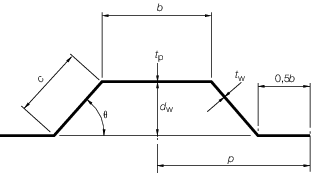
Figure 3.3.3 Dimensions and symbols for corrugated bulkheads
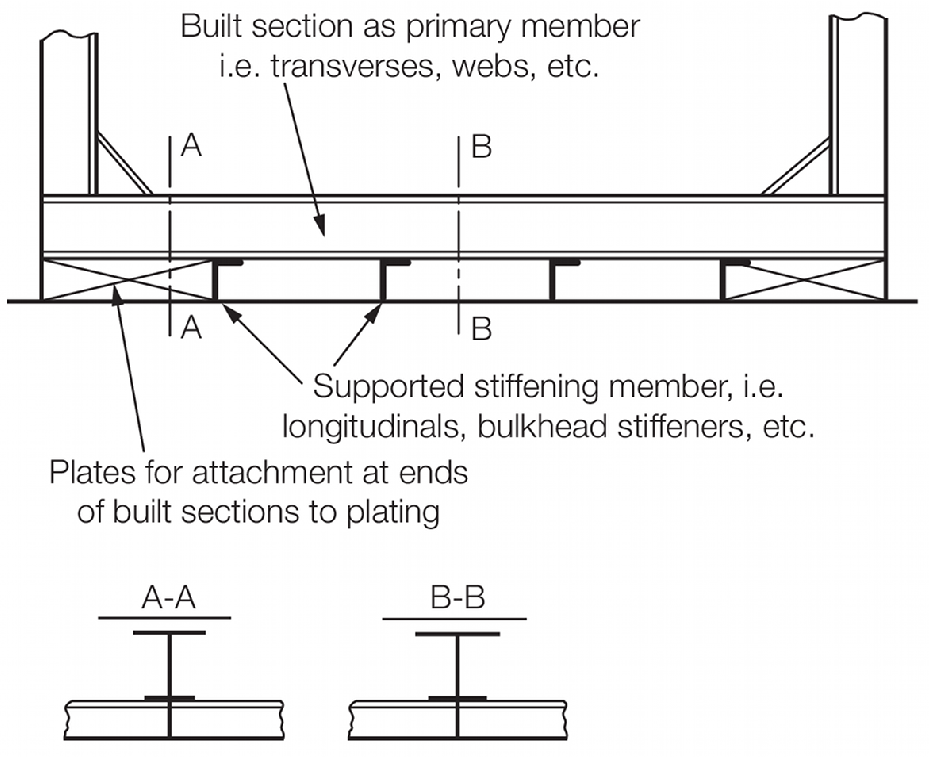
Figure 3.3.4 Rolled or built sections fitted on top of supported stiffening members
3.3 Determination of span point
3.3.1 The effective span, l
e, of a stiffening member is generally less than the overall length,
l, by an amount which depends on the design of the end connections. The span
points, between which the value of l
e is measured, are to be determined as follows:
-
For rolled or built
stiffener sections, swedges and corrugations:
|
|
The span point is to be taken
at the point where the depth of the end bracket, measured from the
face of the stiffener is equal to the depth of the stiffener. Where
there is no Rule end bracket, the span point is to be taken at the end
of the stiffener.
|
-
For primary support
members, i.e. girders, transverses, webs, stringers, etc.:
|
|
The span point is
to be taken at a point distant b
e from the end of the member,
|
where:
See also
Pt 3, Ch 3, 3.2 Geometric properties of section 3.2.1.
3.3.2 It is assumed
that the ends of stiffening members are substantially fixed against
rotation and displacement. If the arrangement of supporting structure
is such that this condition is not achieved, consideration will be
given to the effective span to be used for the stiffener.
3.4 Calculation of hull section modulus
3.4.1 All continuous
longitudinal structural material is to be included in the calculation
of the inertia of the hull midship section, and the lever z is,
except where otherwise specified for particular ship types, to be
measured vertically from the neutral axis to the top of keel and to
the moulded strength deck line at the side. The strength deck is to
be taken as follows:
-
Where there is a
complete upper deck and no effective superstructure, the strength
deck is the upper deck.
-
Where there is an
effective superstructure or a stepped deck the position of the strength
deck will be specially considered.
3.4.2 An effective
superstructure is a superstructure extending over the full breadth
of the ship and which exceeds 0,20L in length or 10 m
whichever is the greater and is situated within the 0,5L region.
3.4.3 Lightening
holes in girders need not be deducted, provided that their depth does
not exceed 20 per cent of the web depth.
3.4.4 Isolated
weld scallops, drain and air holes in longitudinals need not be deducted,
provided that their depth does not exceed 65 mm. In no case is the
opening to be greater than 25 per cent of the web depth. Such openings
are considered isolated if they are spaced not less than 1 m apart.
3.4.5 In general,
isolated deck openings need not be deducted, but compensation may
be required. See individual ship type Chapters.
3.4.6 Where trunk decks or continuous hatch coamings are effectively supported by
longitudinal bulkheads or deep girders, they are to be included in the longitudinal
sectional area when calculating the hull section modulus. The lever zt
is to be taken as:
 m but not less than z
where
|
y
|
= |
horizontal distance from top of continuous strength member to the
centreline of the ship, in metres |
|
z
|
= |
vertical distance from the newtral axis to the moulded deck line
at side, in metres |
|
zc
|
= |
vertical distance from the neutral axis to the top of the
continuous strength member, in metres |
zc and y are to be measured to the point giving the largest
value of zt
|