
Section
3 Design
3.1 Scope
3.1.1 The formulae
given in this Section are applicable to solid crankshafts, having
a main support bearing adjacent to each crankpin, and are intended
to be applied to a single crankthrow analysed by the static determinate
method.
3.1.2 Alternative
methods, including a fully documented stress analysis, will be specially
considered.
3.1.3 Calculations
are to be carried out for the maximum continuous power rating for
all intended operating conditions.
3.1.4 Designs
of crankshafts not included in this scope will be subject to special
consideration.
3.2 Information to be submitted
3.2.1 In addition
to detailed dimensioned plans, the following information is required
to be submitted:
- Engine type – 4SCSA/2SCSA/in line/vee.
- Output power at maximum continuous rating (MCR), in kW.
- Output speed at maximum continuous power, in rpm.
- Maximum cylinder pressure, in bar g.
- Mean indicated pressure, in bar g.
- Cylinder air inlet pressure, in bar g.
- Digitised gas pressure/crank angle cycle for MCR.
- Maximum pressure/speed relationship.
- Compression ratio.
- Vee angle and firing interval (if applicable), in degrees.
- Firing order numbered from driving end, see
Figure 2.3.1 Designation of cylinders.
- Cylinder diameter, in mm.
- Piston stroke, in mm.
- Mass of connecting rod (including bearings), in kg.
- Centre of gravity of connecting rod from large end centre, in
mm.
- Radius of gyration of connecting rod, in mm.
- Length of connecting rod between bearing centres, in mm.
- Mass of single crankweb (indicate if webs either side of pin are
of different mass values), in kg.
- Centre of gravity of crankweb mass from shaft axis, in mm.
- Mass of counterweights fitted (for complete crankshaft) indicate
positions fitted, in kg.
- Centre of gravity of counterweights (for complete crankshaft)
measured from shaft axis, in mm.
- Mass of piston (including piston rod and crosshead where applicable),
in kg.
- All individual reciprocating masses acting on one crank, in kg.
- Material specification(s).
- Specified minimum UTS, in N/mm2.
- Specified minimum yield strength, in N/mm2.
- Method of manufacture.
- Details of fatigue enhancement process (if applicable).
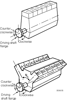
Figure 2.3.1 Designation of cylinders
3.3 Symbols
3.3.1 For the
purposes of this Chapter, the following symbols apply (see also
Figure 2.3.2 Crank dimensions necessary for the calculation of stress concentration factors):
|
h
|
= |
radial
thickness of web, in mm |
|
k
e
|
= |
bending stress factor |
|
B
|
= |
transverse
breadth of web, in mm |
|
D
p, D
j
|
= |
outside diameter of pin or main journal, in
mm |
|
D
pi, D
ji
|
= |
internal diameter of pin or main journal,
in mm |
|
d
o
|
= |
diameter of radial oil bore in crankpin, in mm |
|
F
|
= |
alternating
force at the web centre line, in N |
|
K
1
|
= |
fatigue enhancement factor due to manufacturing process |
|
K
2
|
= |
fatigue enhancement factor due to surface treatment |
|
M
b
|
= |
alternating bending moment at web centre line, in N-mm (NOTE:
alternating is taken to be  range value) range value)
|
|
M
BON
|
= |
alternating bending moment calculated at the outlet of crankpin
oilbore |
|
M
p, M
j
|
= |
undercut of fillet radius into web measured
from web face, in mm |
|
R
p, R
j
|
= |
fillet radius at junction of web and pin or
journal, in mm |
|
T
|
= |
axial
thickness of web, in mm |
|
T
a
|
= |
alternating torsional moment at crankpin or crank journal, in
N-mm (NOTE: alternating is taken to be  range value) range value)
|
|
|
= |

|
|
αB
|
= |
bending
stress concentration factor for crankpin |
|
αT
|
= |
torsional
stress concentration factor for crankpin |
|
βB
|
= |
bending
stress concentration factor for main journal |
|
βQ
|
= |
direct
shear stress concentration factor for main journal |
|
βT
|
= |
torsional
stress concentration factor for main journal |
|
γB
|
= |
bending
stress concentration factor for radially drilled oil hole in the crankpin |
|
γT
|
= |
torsional
stress concentration factor for radially drilled oil hole in the crankpin |
|
σax
|
= |
alternating
axial stress, in N/mm2
|
|
σb
|
= |
alternating
bending stress, in N/mm2
|
|
σBON
|
= |
alternating
bending stress in the outlet of the oil bore, in N/mm2
|
|
σp, σj
|
= |
maximum bending stress in pin and main journal
taking into account stress raisers, in N/mm2
|
|
σBO
|
= |
maximum
bending stress in the outlet of the oil bore, in N/mm2
|
|
σQ
|
= |
alternating
direct stress, in N/mm2
|
|
σu
|
= |
specified
minimum UTS of material, in N/mm2
|
|
σy
|
= |
specified
minimum yield stress of material, in N/mm2
|
|
τa
|
= |
alternating
torsional stress, in N/mm2
|
|
τp, τj
|
= |
maximum torsional stress in pin and main journals taking into
account stress raisers, in N/mm2
|
|
τtob
|
= |
maximum
torsional stress in outlet of crankpin oil bore taking into account
stress raisers, in N/mm2.
|
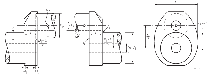
Figure 2.3.2 Crank dimensions necessary for the calculation of stress concentration factors
3.4 Stress concentration factors
3.4.1
Geometric
factors. Crankshaft variables to be used in calculating the
geometric stress concentrations together with their limits of applicability
are shown in Table 2.3.1 Crankshaft variables.
Table 2.3.1 Crankshaft variables
| Variable
|
Range
|
| Lower
|
Upper
|
|
b = B/D
p
|
1,10
|
2,20
|
|
d
j = D
ji/D
p
|
0,00
|
0,80
|
|
d
p = D
pi/D
p
|
0,00
|
0,80
|
|
m
j = M
j/D
p
|
0,00
|
r
jB
|
|
m
p = M
p/D
p
|
0,00
|
r
p
|
|
r
jB = R
j/D
p
|
0,03
|
0,13
|
|
r
jT = R
j/D
j
|
0,03
|
0,13
|
|
r
p = R
p/D
p
|
0,03
|
0,13
|
|
t = T/D
p
|
0,20
|
0,80
|
|
d = d
o/D
p
|
0,00
|
0,20
|
u = U/D
p
See Note 2
|
|
0,50
|
Note
1. Where variables fall outside the
range, alternative methods are to be used and full details submitted
for consideration.
2. A lower limit of u can be
extended down to large negative values provided that:
- (i) If calculated f(rec) < 1 then the factor
f(rec) is not to be considered (f(rec) =
1)
- (ii) If u < –0,5 then f(ut) and f(ru)
are to be evaluated replacing actual value of u by –0,5.
|
3.4.2 Crankpin
stress concentration factors:
Bending
|
αB
|
= |
2,70
f(ut). f(t). f(b). f(r). f(dp). f(dj). f(rec) |
where
|
f(ut) |
= |
1,52 –
4,1t + 11,2t
2 – 13,6t
3 + 6,07t
4 – u (1,86
– 8,26t + 18,2t
2 –
18,5t
3 + 6,93t
4)
– u
2 (3,84 – 25,0t +
70,6t
2 – 87,0t
3 +
39,2t
4)
|
|
f(t) |
= |
2,18t
0,717
|
|
f(b) |
= |
0,684 –
0,0077b + 0,147b
2
|
|
f(r) |
= |
0,208r
p
(–0,523)
|
|
f(dp) |
= |
1 + 0,315(d
p) – 1,52(d
p)2 +
2,41(d
p)3
|
|
f(dj) |
= |
1 + 0,27d
j – 1,02(d
j)2 + 0,531(d
j)3
|
|
f(rec) |
= |
1 + (m
p + m
j) (1,8 + 3,2u)
valid only between u = –0,5 and 0,5
|
Torsion
|
αT
|
= |
0,8
f(ru). f(b). f(t) |
where
|
f(ru) |
= |
r
p
–(0,22 + 0,1u)
|
|
f(b) |
= |
7,9 –
10,65b + 5,35b
2 – 0,857b
3
|
|
f(t) |
= |
t
(–0,145)
|
3.4.3 Crank journal
stress concentration factors:
Bending
|
βB
|
= |
2,71fB(ut). fB(t). fB(b). fB(r).
fB(dj). fB(dp). f(rec)
|
where
|
fB(ut)
|
= |
1,2
– 0,5t + 0,32t
2 – u (0,80 – 1,15t + 0,55t
2)
– u
2 (2,16 – 2,33t +
1,26t
2)
|
|
fB(t)
|
= |
2,24t
0,755
|
|
fB(b)
|
= |
0,562
+ 0,12b + 0,118b
2
|
|
fB(r)
|
= |
0,191r
jB
(–0,557)
|
|
fB(dj)
|
= |
1
– 0,644d
j + 1,23(d
j)2
|
|
fB(dp)
|
= |
1–
0,19d
p + 0,0073(d
p)2
|
|
f(rec) |
= |
1 + (m
p + m
j) (1,8 + 3,2u)
valid only between u = –0,5 and 0,5
|
Direct shear
|
β
Q
|
= |
3,01fQ(u). fQ(t). fQ(b). fQ(r).
fQ(dp). f(rec)
|
where
|
f
Q
(u)
|
= |
1,08 + 0,88u – 1,52(u)2
|
|
fQ(t)
|
= |

|
|
fQ(b)
|
= |
b – 0,5
|
|
fQ(r)
|
= |
0,533r
JB
(–0,204)
|
|
fQ(dp)
|
= |
1
– 1,19d
p + 1,74(d
p)2
|
|
f(rec) |
= |
1 + (m
p + m
j) (1,8 + 3,2u)
valid only between u = –0,5 and 0,5
|
Torsion
|
βT
|
= |
0,8f(ru).
f(b). f(t) |
where
|
f(ru) |
= |
r
jT
– (0,22 + 0,1
u
)
|
|
f(b) |
= |
7,9 –
10,65b + 5,35b
2 – 0,857b
3
|
|
f(t) |
= |
t
(–0,145)
|
3.4.4 Crankpin
oil bore stress concentration factors for radially drilled oil holes:
3.4.5 Where experimental
measurements of the stress concentrations are available, these may
be used. The full documented analysis of the experimental measurements
are to be submitted for consideration.
3.5 Nominal stresses
3.5.1 The nominal alternating bending stress, σb, is to be calculated
from the maximum and minimum bending moment at the web centreline taking into account
all forces being applied to the crank throw in one working cycle with the crankthrow
simply supported at the mid length of the main journals.
3.5.2 Nominal
bending stresses are referred to the web bending modulus.
3.5.3 Nominal
alternating bending stress:
|
σb
|
= |

|
where
|
Zweb
|
= |

|
|
k
e
|
= |
0,8 for crosshead engines |
| = |
1,0 for trunk piston engines. |
3.5.4 Nominal
alternating bending stress in the outlet of the crankpin oil bore:
where
M
BON is taken as the  range value range value
|
M
BON
|
= |
 (M
BOmax – M
BOmin) (M
BOmax – M
BOmin) |
The two relevant bending moments are taken in the crankpin cross-section through the oil
bore.
|
M
BRO
|
= |
bending moment of the radial component of the connecting-rod
force |
|
M
BTO
|
= |
bending moment of the tangential component of the connecting-rod
force |
|
Z
crankpin
|
= |

|
|
Z
crankpin
|
= |
related
to the cross-section of axially bored crankpin. |
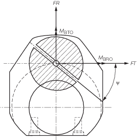
Figure 2.3.3 Crankpin section through the oil bore
3.5.5 The nominal
direct shear stress in the web for the purpose of assessing the main
journal is to be added algebraically to the bending stress, using
the alternating forces which have been used in deriving M
b in Pt 5, Ch 2, 3.5 Nominal stresses 3.5.3.
3.5.6 Nominal
stress is referred to the web cross-section area or the pin cross-section
area as applicable.
3.5.7 Nominal
alternating direct shear stress:
|
σQ
|
= |

|
3.5.8 The nominal
alternating torsional stress, τa, is to be taken into
consideration. The value is to be derived from forced-damped vibration
calculations of the complete dynamic system. Alternative methods will
be given consideration. The engine designer is to advise the maximum
level of alternating vibratory stress that is permitted.
3.5.10 Nominal
alternating torsional stress:
|
τa
|
= |

|
where
|
ZT
|
= |
torsional
modulus of crankpin and main journal |
| = |

|
|
D
|
= |
outside
diameter of crankpin or main journal, in mm |
|
d
|
= |
inside
diameter of crankpin or main journal, in mm. |
τa is to be ascertained from assessment of the torsional vibration
calculations where the maximum and minimum torques are determined for every mass point
of the complete dynamic system and for the entire speed range by means of a harmonic
synthesis of the forced vibrations from the 0,5th order up to and including the 12th
order for 4-stroke cycle engines. Whilst doing so, allowance must be made for the
damping that exists in the system and for unfavourable conditions (misfiring in one of
the cylinders when no combustion occurs but only compression cycle). The speed step
calculation shall be selected in such a way that any resonance found in the operational
speed range of the engine shall be detected.
3.5.11 For the
purpose of the crankshaft assessment, the nominal alternating torsional
stress considered in calculations is to be the highest calculated
value, according to the method described in Pt 5, Ch 2, 3.5 Nominal stresses 3.5.9, occurring at the most torsionally loaded mass point
of the crankshaft system.
3.5.12 The approval
of the crankshaft will be based on the installation having the largest
nominal alternating torsional stress (but not exceeding the maximum
figure specified by the engine manufacturer). For each installation
it is to be ensured by calculation that the maximum approved nominal
alternating torsional stress is not exceeded.
3.5.13 In addition
to the bending stress, σb, the axial vibratory stress,
σax, is to be taken into consideration, for crosshead
type engines. For trunk type engines, σax = 0. The
value is to be derived from forced-damped vibration calculations of
the complete dynamic system. Alternative methods will be given consideration.
The engine designer is to advise the maximum level of alternating
vibratory stress that is permitted. The corresponding crankshaft free-end
deflection is also to be stated.
3.6 Maximum stress levels
3.6.2 Outlet
of crankpin oil bore:
3.6.3 Crank journal
fillet.
3.7 Equivalent alternating stress
3.7.1 Equivalent
alternating stress of the crankpin, σep, or crank journal,
σej, is defined as:
|
σep, σej
|
= |

|
where
|
σ |
= |
σp or
σj N/mm2
|
|
τ |
= |
τp or
τj N/mm2.
|
3.7.2 Equivalent
alternating stress for the outlet of the crankpin oil bore σeob,
is defined as:
3.8 Fatigue strength
3.8.1 The fatigue
strength of a crankshaft is based upon the crankpin and crank journal
as follows:
|
σfp
|
= |

|
To calculate the fatigue strength in the oil bore
area, replace R
p with  do and σfp with σfob. do and σfp with σfob.
|
σfj
|
= |

|
where
|
σu
|
= |
UTS
of crankpin or crank journal as appropriate |
|
K
1
|
= |
fatigue endurance factor appropriate to the manufacturing process |
|
|
= |
1,05 for continuous
grain-flow (CGF) or die-forged |
|
|
= |
1,0 for freeform
forged (without CGF) |
|
|
= |
0,93 for cast steel
manufactured using a LR approved cold rolling process |
|
K
2
|
= |
fatigue enhancement factor for surface treatment. |
|
|
= |
These treatments
are to be applied to the fillet radii. |
A value for K
2 will be assigned upon
application by the engine designers. Full details of the process,
together with the results of full scale fatigue tests will be required
to be submitted for consideration. Alternatively, the following values
may be taken (surface hardened zone to include fillet radii):
|
K
2
|
= |
1,15 for induction hardened |
Where a value of K
1 or K
2 greater than unity is to be applied, then details of the manufacturing
process are to be submitted.
3.9 Acceptability criteria
3.9.1 The acceptability
factor, Q, is to be greater than 1,15:
|
Q |
= |
 for crankpin, journal and the outlet of crankpin oil bore for crankpin, journal and the outlet of crankpin oil bore
|
where
|
σf
|
= |
σfp or σfj or σfob
|
|
σe
|
= |
σep or σej or σeob.
|
3.10 Oil hole
3.10.1 The junction
of the oil hole with the crankpin or main journal surface is to be
formed with an adequate radius and smooth surface finish down to a
minimum depth equal to 1,5 times the oil bore diameter.
3.10.2 Fatigue
strength calculations or alternatively fatigue test results may be
required to demonstrate acceptability.
3.10.3 When
journal diameter is equal to or larger than the crankpin diameter,
the outlets of main journal oil bores are to be formed in a similar
way to the crankpin oil bores, otherwise separate fatigue strength
calculations or, alternatively, fatigue test results may be required.
3.11 Shrink fit of semi-built crankshafts
3.12 Alternative method for calculation of stress concentration factors
3.12.1 LR will give consideration to crankshaft design using an alternative method
given in the LR Guidance Notes for the Calculation of Stress Concentration Factors,
Fatigue Enhancement Methods and Evaluation of Fatigue Tests for Crankshafts.
|