
Section
2 Marking
2.1 General
2.1.1 Each lifting
appliance and each item of loose gear is to be clearly and permanently
marked with its safe working load, with an identification mark to
enable it to be readily related to its appropriate test certificate
and with the mark of the Surveyor or manufacturer who carried out
the proof test.
2.1.2 In view of
the importance of ensuring that each item of loose gear has the correct
safe working load for its particular position in the lifting appliance,
and to facilitate the ordering of replacements, it is recommended
that a Particulars Book or a fully detailed Rigging Plan and Block
List be kept on board. Typical symbols used in rigging plans are given
in Figure 12.2.1 Symbols for fittings used in key
plans or rigging.
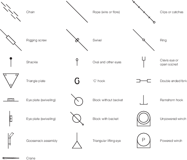
Figure 12.2.1 Symbols for fittings used in key
plans or rigging
2.2 Loose gear
2.2.1 Every item
of loose gear, including lifting beams and similar items, is to be
marked with:
-
The safe working load
of the item, in tonnes. For asymmetric lifting beams, the maximum
reaction at each lifting point is also to be marked.
-
An individual alphanumeric
identification mark to relate it to its test certificate.
-
A mark indicating the
grade of steel in accordance with Table 12.2.1 Material quality grade
marks.
-
The Surveyor’s
or manufacturer’s stamp.
-
For blocks, the maximum
rope diameter for which the block is designed.
-
For lifting beams and
similar items, the tare weight in tonnes.
-
Where appropriate,
an identification mark corresponding to the position of the item on
the ship’s Rigging Plan.
Table 12.2.1 Material quality grade
marks
| Quality grade
mark
|
Grade of steel
|
Ultimate tensile strength,
in N/mm2
|
| L
|
Mild
|
300
|
| M
|
Higher
tensile
|
400
|
| P
|
Alloy
|
500
|
| S
|
Alloy
|
630
|
| T
|
Alloy
|
800
|
2.2.2 Permanent
identification marks or symbols are to be made, with stamps having
rounded profiles (low stress stamps). The number of marks on an item
is to be kept to the minimum.
2.2.3 The use of
fractions and oblique strokes is to be avoided and a dot or hyphen
is preferable to a dividing line. Values of SWL are, generally, to
be marked to one place of decimals (except for 0,25 and 0,75) up to
100 t and in integers thereafter. The word ‘tonnes’ may
be abbreviated to ‘t’.
2.2.4 Recommended
sizes of marks are given in Table 12.2.2 Size of marks based
on the diameter of the part to be marked or on the SWL of the item
as appropriate. Typical arrangements of marks are shown in Figure 12.2.2 Typical marks for loose
gear.
Table 12.2.2 Size of marks
| Item
|
Diameter of part to be marked,
in mm
|
SWL of item, in tonnes
|
Recommended size of mark,
in
mm
|
| Chains, links, rings,
shackles, eyes (without collar), swivels
|
Less
than 12,5
|
|
3,0
|
| 12,5
to 26
|
|
4,5
|
| Over
26
|
|
6,0
|
| Eyes (with collar),
triangle plates, rope sockets, hooks, blocks
|
|
Up to
2
|
3,0
|
| 2 to 8
|
4,5
|
| Over 8
|
6,0
|
| Lifting
beams, spreaders, frames
|
|
All
|
Minimum 75
|
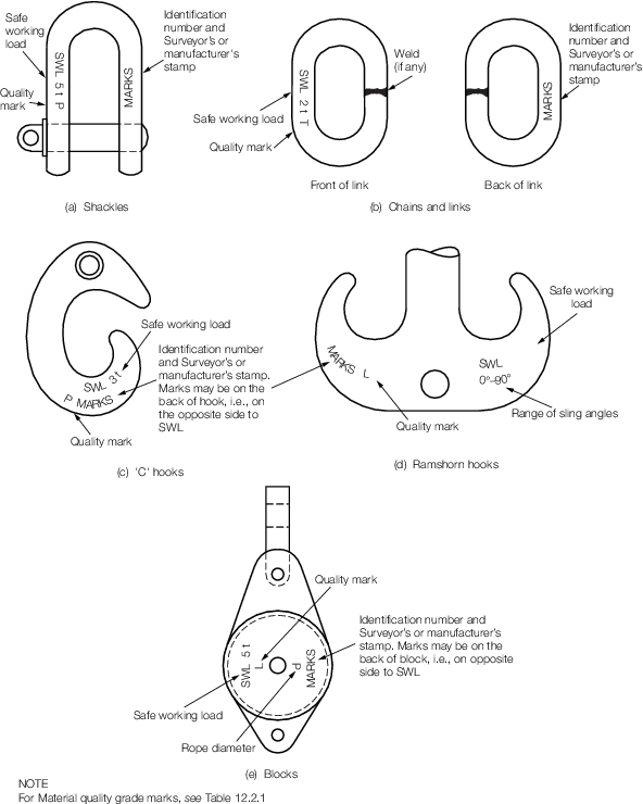
Figure 12.2.2 Typical marks for loose
gear
2.3 Steel wire and fibre ropes, including slings
2.3.1 The following
information is to be marked on a disc or tally attached to the rope
or sling, or an approved electronic capture system:
-
An individual identification
mark to relate the rope to its test certificate.
-
The Surveyor’s
or manufacturer’s stamp.
2.3.3 Markings
on slings are also to include the number of legs and the safe working
load in straight lift and when the angle between the legs and the
vertical is 45°.
2.3.4 The identification
mark on synthetic or fibre slings is also to show its:
- SWL in straight lift;
- SWL when the angle between the legs and the vertical is 45°;
- Material;
- Nominal length;
- Manufacturer’s or supplier’s name.
2.4 Derricks, cranes and launch and recovery systems for diving operations
2.4.1 Every lifting
appliance is to be conspicuously and permanently marked near the heel
of the boom, jib or equivalent component with its safe working load
and the minimum operating angle or limiting radius as indicated in Table 12.2.3 Typical marks on lifting
appliances.
Table 12.2.3 Typical marks on lifting
appliances
| Description
|
Mark
|
| Swinging
derrick with boom as normally rigged
|
SWL 10 t
(30°)
|
| Swinging
derrick with alternative rig
|
SWL 3/10
t (30°)
|
| Derricks
used in union purchase to be marked on inboard side of boom
|
SWL (U)
3 t
|
| Crane of
constant capacity over full range of radii
|
SWL 10 t
(4 m/20 m radius)
|
| Crane of
variable load/radius characteristics
|
A plate
indicating the characteristics is to be permanently attached to the
crane
|
2.4.2 Where more
than one method of rig is possible, or, for derricks, where union
purchase operation is proposed, the safe working load for each method
of rig is to be marked.
2.4.3 The letters
and numbers are to be not less than 75 mm high and painted in yellow
or white on a dark background or black on a light background.
2.4.4 The heel
fitting of the appliance is to be marked with the number of the relevant
test certificate and with the Surveyor’s stamp. The stamps are
to have rounded profiles (low stress stamps).
|
| Copyright 2026 Clasifications Register Group Limited, International Maritime Organization, International Labour Organization or Maritime
and Coastguard Agency. All rights reserved. Clasifications Register Group Limited, its affiliates and subsidiaries and their respective
officers, employees or agents are, individually and collectively, referred to in this clause as 'Clasifications Register'. Clasifications
Register assumes no responsibility and shall not be liable to any person for any loss, damage or expense caused by reliance
on the information or advice in this document or howsoever provided, unless that person has signed a contract with the relevant
Clasifications Register entity for the provision of this information or advice and in that case any responsibility or liability is
exclusively on the terms and conditions set out in that contract.
|
 |
|