
Section
5 Local strength
5.1 General
5.2 Modulus of stiffeners, frames and longitudinals
5.2.1 For longitudinals, side frames and bulkhead stiffeners, the section modulus
required by the appropriate formula is generally applicable to that of the section in
association with 600 mm, or 40t, whichever is the greater, of attached plating.
Where the attached plating is of varying thickness, the mean thickness over the
appropriate span is to be used.
5.3 Tank plating
5.3.1 The thickness of boundary plating in ballast tanks, oil tanks, freshwater
tanks, and sewage tanks is to be not less than:
or 7,5 mm whichever is the greater
where
|
s
|
= |
stiffener
spacing, in mm |
|
f
|
= |
 but need not to be taken greater than 1,0 but need not to be taken greater than 1,0 |
|
ρ |
= |
specific gravity of liquid carried in tank, but is not to be taken
less than 1,025 |
|
h
|
= |
maximum
head, in metres, obtained from the hydrostatic curves for that location
and related to a point one-third of the height of the plate. If the
plate is located in that part of the tank containing the air cushion,
then the head should be extended to the lower boundary of the air
cushion. For internal transverse or longitudinal watertight bulkheads, see
Pt 2, Ch 1, 1.6 Data required 1.6.1.(h)
|
|
l |
= |
overall
length of the stiffener or length between span points, in metres, see
Figure 1.5.1 Span points.
|
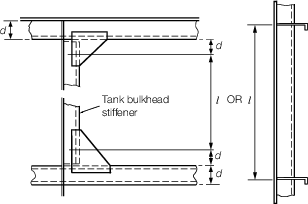
Figure 1.5.1 Span points
5.4 Framing or tank stiffeners
5.4.1 The minimum
section modulus of stiffeners associated with plating in ballast tanks
is to be derived from the following:
5.4.2 The effective
section modulus of any transverse, web, stringer or girder is given
by:
where
|
a |
= |
the area of the face plate of the member, in cm2 |
|
dw |
= |
the depth, in mm, of the web between the inside of the face plate and the
attached plating. Where the member is at right angles to a line of corrugations,
the minimum depth is to be taken |
|
tw |
= |
the thickness of the web of the section, in mm |
|
A |
= |
the area, in cm2, of the attached plating, see
Pt 2, Ch 1, 5.4 Framing or tank stiffeners 5.4.4. |
If the calculated value of A is less than the face area a, then A
is to be taken as equal to a.
5.4.3 The effective area of attached load bearing plating, A, for transverses, webs,
stringers or girders, is to be determined as follows:
- For a member attached to plane plating:
|
A |
= |
10K
b
tp cm2, but is not to be taken less than
a. |
- For a member attached to corrugated plating and parallel to the
corrugations:
|
A |
= |
10b
tp cm2, but is not to be taken less than
a. |
- For a member attached to corrugated plating and at right angles to
the corrugations: A is to be taken as equivalent to the area of the face
plate of the member.
where
|
b |
= |
the actual width, in metres, of the load-bearing plating, i.e.
for (a) one-half of the sum of spacings between parallel adjacent members or
equivalent supports, or for (b) the breath of flat panel of corrugated
bulkhead, see
Figure 1.5.2 Corrugation dimensions
|
|
K |
= |
load bearing factor to be taken as  , but is not to exceed 1,0 , but is not to exceed 1,0 |
|
l |
= |
the overall length, in metres, see
Figure 1.5.1 Span points
|
|
tp |
= |
the thickness, in mm, of the attached plating. Where this
varies, the mean thickness over the appropriate span is to be used, see
Figure 1.5.2 Corrugation dimensions. |
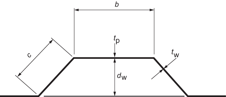
Figure 1.5.2 Corrugation dimensions
5.4.4 For girders, etc. which are symmetrical on each side of the bulkhead, the
attached plating is to be ignored and the effective section modulus is given by:
5.5 Top deck plating
5.5.1 The thickness of plating for the middle 0,4L
D is to be as required for longitudinal strength. For 0,1L
D, at each end of the dock, the thickness is not to be less than 6,5 mm,
(with an increase of 3 per cent for every 25 mm that the spacing of longitudinals
exceeds 610 mm), unless local conditions or transverse strength considerations require a
greater thickness. For the intermediate lengths the thickness of the deck is to be
given proportionate values.
5.6 Top deck longitudinals
5.6.1 The top
deck should, in principle, be stiffened longitudinally for the middle
0,4L
D. The scantlings will generally be those
required to obtain the area necessary for the section modulus derived
from longitudinal strength considerations but are to be not less than
specified in Pt 2, Ch 1, 5.6 Top deck longitudinals 5.6.2 for longitudinals
at the ends.
5.6.2 For 0,1L
D, at each end of the dock, the scantlings of the longitudinals are to be
such that the stress under a loading of 14,37 kN/m2 does not exceed 131
N/mm2. The loading may be required to be increased to suit the special
requirements of a particular dock. The scantlings of the longitudinals in the
intermediate lengths are to be interpolated between those required for the middle and
end portions.
5.7 Safety deck plating
5.7.1 The thickness of plating of the safety deck, is to be not less than:
|
t |
= |
 |
or 7,5 mm whichever is the greater
where
|
s
|
= |
stiffener
spacing, in mm |
|
f |
= |
 but need not to be taken greater than 1,0 but need not to be taken greater than 1,0 |
|
C
|
= |
stowage
rate, in m3/tonne, but is to be taken as not less than
1,39 m3/tonne
|
|
h
|
= |
height
from top of safety deck beam to top of upper deck beam at side |
|
l |
= |
overall
length of beam or longitudinal between support points, in metres. See
Figure 1.5.1 Span points.
|
5.7.2 Where
air pipes project into the wing ballast tanks (see
Pt 2, Ch 1, 6.1 Air pipes under safety deck 6.1.1), it may be that the pressure
in the air cushion exceeds the loading obtained from the above stowage
rate and head, in which case the scantlings are to be calculated on
the basis of this higher loading.
5.7.3 The section
modulus of the beams or longitudinals under the safety deck, including
associated plating, is to be in accordance with the following:
where l, h, s and C are as defined in Pt 2, Ch 1, 5.7 Safety deck plating 5.7.1.
5.8 Framing
5.9 Transverse and web frames
5.9.2 The loading on deep side frames and bottom transverses is to be obtained
from an analysis of the hydrostatic curves. The permissible stress in transverses and
deep frames is to be 131 N/mm2.
5.10 Cross ties
5.10.1 The
sectional area of cross ties, where fitted between the inner and outer
wing walls, is to be not less than:
where
|
h
|
= |
the
maximum head, in metres, at the cross tie under consideration, and
is assumed to occur when the ballast water is level with that tie
and the dock is lifting to its maximum capacity. The required value
is to be obtained from an analysis of the hydrostatic curves |
|
s
|
= |
spacing
of transverses, in metres |
|
le
|
= |
0,7
of total span of cross tie, in metres |
|
v
|
= |
one-half
the distance between the centre of the adjacent cross ties and the
centre of the bottom or deck transverse, in metres |
|
r
|
= |
minimum
radius of gyration of pillar cross-section, in mm. |
As a first approximation, A may be taken as:
and the radius of gyration estimated for a suitable
section having this area. If the area calculated using this radius
of gyration differs by more than 10 per cent from the first approximation,
a further calculation using the radius of gyration corresponding to
the mean area of the first and second approximation is to be made.
5.10.2 For
the sides of hollow square cross ties or web plates of Channel or I
sections, the ratio of the breadth to the thickness is not to exceed:
whichever is the greater. The thickness of hollow
square cross ties is to be not less than 7,5 mm.
5.10.3 For
ordinary angle or channel sections, the ratio of the breadth to the
thickness of the flanges is not to exceed:
whichever is the greater.
5.10.4 For
fabricated sections or the flanges of I section pillars, the
ratio of the breadth to the thickness of face plates is not to exceed:
whichever is the greater.
5.10.5 Diagonal
cross ties will be specially considered.
5.11 Watertight bulkhead plating and stiffeners
5.12 Non-watertight floors and side girders
5.12.1 The
spacing of open floors under pontoon/caisson deck should in principle
be not greater than 6,0 m. Where larger spacings are proposed, direct
calculations will be necessary to demonstrate their suitability.
5.12.2 Side girders below pontoon deck should be designed to withstand localised
loads in way of side blocks where appropriate.
5.13 Local strength of the structure in way of keel blocks and supporting
structure
5.13.1 The
loading to be taken (over the whole length of the dock) by the keel
blocks and supporting structure is to be:
where the spacing between keel blocks is significant the loading may be required to be
increased.
5.14 Platforms extending from ends of dock
5.14.1 The loading on these structures is generally to be assumed as 5750
N/m2. If a heavier loading is anticipated or required, the plans are to be
marked accordingly.
Table 1.5.1 Non-watertight pillar
bulkheads
| Parameter
|
Requirement
|
|
(1) Minimum thickness of plating
|
7,5 mm in pontoons
|
|
(2) Maximum stiffener spacing
|
1500 mm
|
|
(3) Minimum depth of stiffeners or corrugations
|
100
mm
|
150
mm
|
|
(4) Cross-sectional area (including plating) for rolled,
built or swedged stiffeners supporting beams, longitudinals, girders or
transverses
|
(a)
where  ≤ 80, ≤ 80,
|
A = A
1
|
|
|
(b)
where  ≥ 120, ≥ 120,
|
A = A
2
|
|
|
(c)
where 80 <  < 120, < 120,
|
A is obtained by interpolation between A
1 and A
2
|
| (5) Cross-sectional area (including
plating) for symmetrical corrugation
|
(a) where  ≤ ≤ 
|
A = A
1
|
|
|
(b) where  ≥ ≥ 
|
A = A
2
|
| Symbols
|
|
A
|
= |
cross-sectional area of stiffener and attached
plating, in cm2
|
|
A
1
|
= |

|
As a first approximation A
1 may be taken as 
|
A
2
|
= |

|
As first approximation A
2 may be taken as 
|
P
|
= |
load, in kN, supported by the pillar. The greater of
either the load due to the head of water acting on the pontoon deck
and bottom plating (obtainable by analysis of hydrostatic curves),
or the load due to the weight of the ship on the keel blocks as
detailed in Pt 2, Ch 1, 5.13 Local strength of the structure in way of keel blocks and supporting structure 5.13.1
|
|
le
|
= |
effective length of pillar, in metres, and is taken
as 0,8 of the total depth of the non-watertight girder or
bulkhead |
|
s
|
= |
spacing of stiffeners, in mm |
|
r
|
= |
radius of gyration of stiffener and attached plating,
in mm |
| = |
 mm for rolled, built or swedged stiffeners mm for rolled, built or swedged stiffeners |
| = |
 mm for symmetrical corrugation mm for symmetrical corrugation |
|
I |
= |
moment of inertia of stiffener and attached plating,
in cm4 |
|
λ |
= |

|
d
w, t
p, b, c are as defined in Figure 1.5.2 Corrugation dimensions
|
5.15 Swing bridges at end of dock
5.15.1 The loading on this connecting bridge is generally to be assumed as 3590
N/m2. If a heavier loading is anticipated or required, the plan is to be
marked accordingly.
|