
Section
2 Structural idealization for pontoons
2.1 Geometric properties of section
2.1.1 The
symbols used in this sub-Section are defined as follows:
|
b
|
= |
the
actual width, in metres, of the load-bearing plating, i.e. one-half
of the sum of spacings between parallel adjacent members or equivalent
supports |
|
t
p
|
= |
the thickness of the attached plating in mm. Where this varies,
the mean thickness over the appropriate span is to be used |
2.1.2 The
effective geometric properties of rolled or built sections may be
calculated directly from the dimensions of the section and associated
effective area of attached plating. Where the web of the section is
not normal to the attached plating, and the angle exceeds 20°,
the properties of the section are to be determined about an axis parallel
to the attached plating.
Table 3.2.1 Section geometry factor, f
|
|
f
|
|
f
|
| 0,5
|
0,19
|
3,5
|
0,69
|
| 1,0
|
0,30
|
4,0
|
0,76
|
| 1,5
|
0,39
|
4,5
|
0,82
|
| 2,0
|
0,48
|
5,0
|
0,88
|
| 2,5
|
0,55
|
5,5
|
0,94
|
| 3,0
|
0,62
|
6 and above
|
1,00
|
Note Intermediate values to be obtained by linear
interpolation.
|
2.1.3 The
geometric properties of rolled or built stiffener sections and of
swedges are to be calculated in association with the effective area
of attached load bearing plating of thickness t
p and
of width 600 mm or 40t
p whichever is the greater.
In no case, however, is the width of plating to be taken as greater
than either the spacing of the stiffeners or the width of the flat
plating between swedges, whichever is appropriate. The thickness, t
p, is the actual thickness of the attached plating.
Where this varies, the mean thickness over the appropriate span is
to be used.
2.1.4 The
effective section modulus of a corrugation over a spacing p is
to be calculated from the dimensions and, for symmetrical corrugations
may be taken as:
where d
w, b, t
p, c and t
w are
measured in mm, and are as shown in Figure 3.2.1 Corrugated section The value of b is to be taken not greater
than:
|
|
= |
 for welded corrugations for welded corrugations |
|
|
= |
 for cold formed corrugations for cold formed corrugations |
|
|
= |
The value of θ
is to be not less than 40°. |
The moment of inertia is to be calculated from:
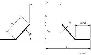
Figure 3.2.1 Corrugated section
2.1.5 The
section modulus of a double plate bulkhead over a spacing b may
be calculated as:
where d
w, b, t
p and t
w are measured,
in mm, and are as shown in Figure 3.2.2 Double plate bulkhead section
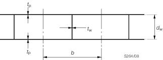
Figure 3.2.2 Double plate bulkhead section
2.1.6 The
effective section modulus of a built section may be taken as:
where
|
a
|
= |
the
area of the face plate of the member, in cm2
|
|
d
w
|
= |
the depth, in mm, of the web between the inside of the face
plate and the attached plating. Where the member is at right angles
to a line of corrugations, the minimum depth is to be taken |
|
t
w
|
= |
the thickness of the web of the section, in mm |
|
A
|
= |
the
area of the attached plating in cm2, see
Pt 3, Ch 3, 2.1 Geometric properties of section 2.1.7. If the calculated value
of A is less than the face area a, then A is to be taken as equal to a.
|
2.1.7 The
geometric properties of primary support members (i.e. girders, transverses,
webs, stringers, etc.) are to be calculated in association with an
effective area of attached load bearing plating, A, determined
as follows:
-
For a member
attached to plane plating:
where b is as defined in Pt 3, Ch 3, 2.1 Geometric properties of section 2.1.1.
-
For a member
attached to corrugated plating and parallel to the corrugations (where b is as defined in Pt 3, Ch 3, 2.1 Geometric properties of section 2.1.4, see also
Figure 3.2.1 Corrugated section):
-
For a member
attached to corrugated plating and at right angles to the corrugations:
A is to be taken as equivalent to the area of the
face plate of the member.
2.2 Determination of span point
2.2.1 The
effective length, l
e, of a stiffening member
is generally less than the overall length, l, by an amount
which depends on the design of the end connections. The span points,
between which the value of l
e is measured,
are to be determined as follows:
-
For rolled
or built secondary stiffening members:
The span point is to be taken at the point where the depth of
the end bracket, measured from the face of the secondary stiffening
member is equal to the depth of the member. Where there is no end
bracket the span point is to be measured between primary member webs.
For double skin construction the span may be reduced by the depth
of the primary member web stiffener, see
Figure 3.2.3 Span points
-
For primary
support members:
The span point is to be taken at a point distant b
e from the end of the member (see
Figure 3.2.3 Span points), where:
2.2.2 Where
the stiffener member is inclined to a vertical or horizontal axis
and the inclination exceeds 10°, the span is to be measured along
the member.
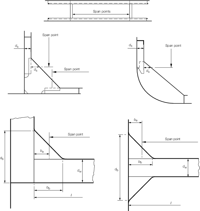
Figure 3.2.3 Span points
2.2.3 It
is assumed that the ends of stiffening members are substantially fixed
against rotation and displacement. If the arrangement of supporting
structure is such that this condition is not achieved, consideration
will be given to the effective span to be used for the stiffener.
|