
Section
3 Hull envelope plating
3.1 Bottom shell plating
3.1.1 The
bottom shell plating thickness is to comply with the requirements
of Table 4.3.1 Bottom shell and bilge
plating.
Table 4.3.1 Bottom shell and bilge
plating
| Location
|
Longitudinal framing
|
Transverse framing
|
|
(1) Bottom plating
|
The greater of the following:
(a) 
(b) 
|
The greater of the following:
(a) 
(b) 
|
L, D,
T as defined in Pt 3, Ch 4, 1.3 Symbols and definitions
|
s
|
= |
spacing of frames, beams or longitudinals, in mm |
|
S
|
= |
spacing or mean spacing of girders, transverses or
floors, in metres |
|
k
|
= |
material factor, see
Pt 3, Ch 2, 1.2 Steel
|
|
C
w
|
= |
wave head, in metres |
| = |
7,71 × 10⁻²
L.e-0,0044L
|
| = |
where e is the base of natural logarithms
2,71828 |
|
f
1
|
= |

|
|
h
T2
|
= |
(T+0,5C
w), in metres but need not be taken greater than
1,2T m |
|
s
1
|
= |
s, but is not to be taken less than the smaller of  or 700 mm or 700 mm |
|
3.2 Side and end shell plating
3.2.2 Sea
inlets, or other openings, are to have well rounded corners and so
far as possible, are to be kept clear of the bilge radius, if any.
Openings on, or near to, the bilge radius are to be elliptical. The
thickness of sea inlet box plating is to be the same as the adjacent
shell, but not less than 12,5 mm and need not exceed 25 mm.
3.3 Deck plating
3.3.2 Additionally,
where the pontoon deck will be subject to vehicular loading, the plating
is to be designed for the maximum tyre print and axle loads that will
use the linkspan.
3.3.3 Details
of the vehicle types using the deck are to be submitted. These are
to include:
- Wheel loads.
- Axle and wheel spacings.
- Tyre print dimensions.
- Type of tyre fitted (solid or pneumatic).
3.3.4 The
deck plating thickness, t, is to be not less than:
3.3.5 Where
a transversely framed deck contributes to the hull girder strength
or where secondary stiffening is fitted perpendicular to the direction
of vehicle lanes, the thickness, t, derived from Pt 3, Ch 4, 3.3 Deck plating 3.3.4 is to be increased by
1,0 mm.
3.3.6 Where it is proposed to carry tracked vehicles, the patch dimensions may be
taken as the track print dimensions and Pw is to be taken as half the
total weight of the vehicle. The wear and wastage allowance, tc, is to
be increased by 0,5 mm.
3.3.7 Deck
fittings in way of vehicle lanes are to be recessed.
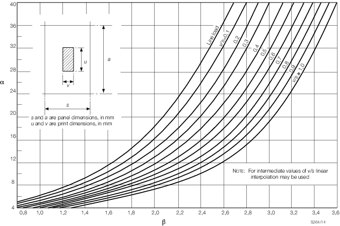
Figure 4.3.1 Tyre print chart
Table 4.3.2 Side and end shell plating
| Location
|
Thickness, in mm
|
| Longitudinal framing
|
Transverse framing
|
|
(1) Side shell clear of sheerstrake
|
(a) Above  from the base: from the base:
The greater of the
following:
(i) 
(ii) 
|
(a) Within  from the gunwale: from the gunwale:
The greater of the
following:
(i) 
(ii) 
|
(b) Up to  from the base: from the base:
The greater of the
following:
(i) 
(ii) 
|
(b) Up to  from mid-depth: from mid-depth:
The greater of the
following:
(i) 
(ii) 
|
|
|
(c) Within  from base: from base:
(i) 
(ii) 
|
L, D as defined in Pt 3, Ch 4, 1.3 Symbols and definitions
|
L
1
|
= |
as defined in Figure 4.1.1 Pontoon dimensions
|
|
k
|
= |
material factor see
Pt 3, Ch 2, 1.2 Steel
|
|
C
w
|
= |
wave head, in metres |
| = |
7,71 × 10⁻²
L.e-0,0044L
|
| = |
where e is the base of natural logarithms
2,71828 |
|
f
1
|
= |

|
|
h
T1
|
= |
T + C
w, in metres but need not be taken greater than
1,36T m |
|
h
T2
|
= |
(T + 0,5C
w), in metres but need not be taken greater than
1,2T m |
|
s
1
|
= |
s, but is not to be taken less than the smaller of  or 700 mm or 700 mm |
|
s
|
= |
spacing of frames, beams or longitudinals, in mm |
|
Table 4.3.3 Strength/weather deck
plating
| Location
|
Minimum thickness, in mm
|
| Longitudinal framing
|
Transverse framing
|
|
(1) Deck plating
|
The greater of the following:
(a) 
(b) 
|
The greater of the following:
(a) 
(b) 
|
|
(2) In way of the crown of a tank
|
or as (1) whichever is the greater, but not less than 6,5
mm
|
L as defined in Pt 3, Ch 4, 1.3 Symbols and definitions
|
ρ |
= |
relative density (specific gravity) of liquid carried
in a tank, but is not to be taken less than 1,025 |
|
k
|
= |
material factor see
Pt 3, Ch 2, 1.2 Steel
|
|
s
|
= |
spacing of frames, beams or longitudinals, in mm |
|
S
|
= |
spacing or mean spacing or girders, transverses or
floors, in metres |
|
f
|
= |
 but not to be taken greater than 1,0 but not to be taken greater than 1,0 |
|
f
1
|
= |

|
|
h
4
|
= |
tank head, in metres, see
Table 4.5.1 Watertight and ballast tank
bulkhead scantlings
|
|
s
1
|
= |
s, but is not to be taken less than the smaller of  or 700 mm or 700 mm |
|
Table 4.3.4 Corrected patch loading
| Expression
|
|
|
|
|
v
1 = v, but not > s
|
|
u
1 = u, but not > a
|
|
|
for u ≤ (a - s)
|
|
|
for a ≥ u > (a - s)
|
|
|
for u > a
|
|
|
for v < s
|
|
|
for 1,5 >  ≥ 1,0 ≥ 1,0
|
|
|
for  ≥ 1,5 ≥ 1,5
|
|
|
a, s,
u, and v as defined in Figure 4.3.1 Tyre print chart
|
n
|
= |
tyre correction factor, see
Table 4.3.5 Tyre correction factor, n
|
|
P
w
|
= |
load, in tonnes, on the tyre print. For closely
spaced wheels the shaded area shown in Figure 4.3.1 Tyre print chart may be taken as the
combined print. |
|
P
1
|
= |
corrected patch load, in tonnes |
|
λ
|
= |
dynamic magnification factor |
|
φ1
|
= |
patch aspect ratio correction factor |
|
φ2
|
= |
patch aspect ratio correction factor |
|
φ3
|
= |
wide patch load factor |
|
Table 4.3.5 Tyre correction factor, n
| Number of wheels in idealized
patch
|
Pneumatic tyres
|
Solid rubber tyres
|
Steel or solid tyres
|
| 1
|
0,6
|
0,8
|
1,0
|
| 2 or more
|
0,75
|
0,9
|
1,0
|
|