
Section
2 Aerodynamic data
2.1 Wind force coefficient, C
f
2.1.1 The
force coefficient for various structural components is given in Table 9.2.1 Force coefficient (Cf). The values for
individual members vary according to the aerodynamic slenderness and
in the case of large box sections, with the section ratio.
Table 9.2.1 Force coefficient (Cf)
| Type
|
Description
|
Aerodynamic slenderness l/b or
l/D
|
| 5
|
10
|
20
|
30
|
40
|
50
|
| Force coefficient C
f
|
| Individual members
|
Rolled
sections, rectangles, hollow sections, flat plates, box section with
b or d less than 0,5m
|
1,30
|
1,35
|
1,60
|
1,65
|
1,70
|
1,80
|
| Circular section, where
|
DV
s < 6,0 m2/s
|
0,75
|
0,80
|
0,90
|
0,95
|
1,00
|
1,10
|
|
|
DV
s ≥ 6,0 m2/s
|
0,6
|
0,65
|
0,70
|
0,70
|
0,75
|
0,80
|
|
|
|
b/d
|
|
|
|
|
|
|
| Box section with
b or d greater than 0,5 m
|
≥ 2,00
|
1,55
|
1,75
|
1,95
|
2,10
|
2,20
|
|
|
|
|
1,00
|
1,40
|
1,55
|
1,75
|
1,85
|
1,90
|
|
|
|
|
0,50
|
1,00
|
1,20
|
1,30
|
1,35
|
1,40
|
|
|
|
|
0,25
|
0,80
|
0,90
|
0,90
|
1,00
|
1,00
|
|
| Single lattice
frames
|
Flat
sided sections
|
1,70
|
| Circular section, where
|
DV
s < 6,0 m2/s
|
1,20
|
|
|
DV
s ≥ 6,0 m2/s
|
0,80
|
| Machinery houses,
etc.
|
Rectangular clad
structures on ground or solid base (air flow beneath structure
prevented)
|
1,10
|
|
D
|
= |
the diameter of the section, in metres |
|
V
s
|
= |
the design wind speed, in m/s |
|
2.2 Aerodynamic slenderness and section ratio
2.3 Shielding and solidity factors
2.3.1 Where
a structure consists of a framework of members such that shielding
takes place, the wind force on the windward frame or member and on
the sheltered parts of those behind it is calculated using the appropriate
force coefficient. The force coefficient on the sheltered parts is
to be multiplied by a shielding factor η. The values of η
vary with the solidity and spacing ratio of the framework. Values
of η are given in Table 9.2.2 Shielding factor(n) for
the solidity and spacing ratio as defined in Figure 9.2.2 Solidity ratio and spacing ratio.
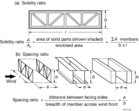
Figure 9.2.2 Solidity ratio and spacing ratio
Table 9.2.2 Shielding factor(n)
| Spacing ratio
|
Solidity ratio A/A
e
|
|
a/b
|
0,1
|
0,2
|
0,3
|
0,4
|
0,5
|
0,6
|
| 0,5
|
0,75
|
0,4
|
0,32
|
0,21
|
0,15
|
0,1
|
| 1,0
|
0,92
|
0,75
|
0,59
|
0,43
|
0,25
|
0,1
|
| 2,0
|
0,95
|
0,8
|
0,63
|
0,5
|
0,33
|
0,2
|
| 4,0
|
1
|
0,88
|
0,75
|
0,66
|
0,55
|
0,45
|
| 5,0
|
1
|
0,95
|
0,88
|
0,81
|
0,75
|
0,68
|
| 6,0
|
1
|
1
|
1
|
1
|
1
|
1
|
2.3.2 Where
a structure consists of a number of identical frames or members spaced
equidistantly behind each other in such a way that each frame shields
those behind it, the wind load is to be obtained from the following
expression:
and A and P are as defined in Pt 3, Ch 3, 3.6 Wind loading 3.6.3.
2.4 Tower sections
2.4.1 For
latticed tower structures, the `face on' wind force based on the solid
area of the windward face is to be calculated using the following
factored pressures:
-
For towers
composed of flat-sided sections:
-
For towers
composed of circular sections:
where
and
The value of η is taken from Table 9.2.2 Shielding factor(n) for a/b =
1,0 according to the solidity ratio of the windward face.
2.4.2 The
maximum wind load on a square section tower occurs when the wind blows
on to a corner and is to be taken as 1,2 times the `face on' load.
|