
Section
6 Forgings for turbines
6.1 Scope
6.1.1 Provision
is made in this Section for ferritic steel forgings for turbine rotors,
discs and spindles, turbine-driven generator rotors and compressor
rotors.
6.1.2 Plans for
rotor forgings are to state whether the rotor is intended for propulsion
or auxiliary machinery and the shaft power of auxiliary turbines.
In the case of a rotor which is to be tested for thermal stability,
the maximum operating temperature and the proposed test temperature
are also to be stated.
6.1.3 Specifications
of alloy steel forgings giving the proposed chemical composition,
heat treatment and mechanical properties are to be submitted for approval
with the plans of the components.
6.1.4 Where it
is proposed to use rotors of welded construction, the compositions
of the steels for the forgings are to be submitted for special consideration,
together with details of the proposed welding procedure. Welding procedure
tests may be required.
6.2 Manufacture
6.2.1 Forgings
are to be manufactured in accordance with the requirements of Ch 5, 1 General requirements, except that for rotors the forging
reduction is to be not less than 2,5 to 1. Where an upsetting operation
is included in the manufacturing procedure, the above requirement
applies to the cross-sectional area of the upset bloom and not to
that of the ingot.
6.3 Chemical composition
6.4 Heat treatment
6.4.1 Forgings
are to be supplied in the heat treated condition, and the thermal
treatment at all stages is to be such as to avoid the formation of
hair-line cracks. At a suitable stage of manufacture, the forgings
are to be reheated above the upper critical point to refine the grain,
cooled in an approved manner and then tempered to produce the desired
mechanical properties.
6.4.2 Where forgings
receive their main heat treatment before machining, they are to be
stress relieved after rough machining. Forgings which are heat treated
in the rough machined condition need not be stress relieved provided
that they have been slowly cooled from the tempering temperature.
6.4.3 The tempering
and stress relieving temperatures are to be not less than 550°C
for carbon and carbon-manganese steels, and not less than 600°C
for alloy steels. The holding times and subsequent cooling rates are
to be such that the forging in its final condition is free from harmful
residual stresses.
6.4.4 Details of
the proposed heat treatment for rotors of welded construction are
to be submitted for approval.
6.5 Mechanical tests
6.5.1 At least
one tensile test specimen, cut in a longitudinal direction, is to
be taken from each rotor forging. For forgings exceeding both 3 tonnes
in mass and 2000 mm in length, tests are to be taken from each end.
6.5.2 For rotor
forgings of all main propulsion machinery and of auxiliary turbines
exceeding 1100 kW, tangential and, where the dimensions permit, radial
tensile tests are to be taken from the end of the body corresponding
to the top end of the ingot, see
Figure 5.6.1 Test positions for turbine rotor
forgings.
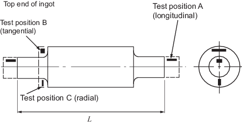
Figure 5.6.1 Test positions for turbine rotor
forgings
6.5.4 For the tests required by Ch 5, 6.5 Mechanical tests 6.5.1 to Ch 5, 6.5 Mechanical tests 6.5.3, sufficient test material is to be left on each forging
and is not to be removed until all heat treatment, including stress relieving, has been
completed. In this connection, a thermal stability test does not form part of the heat
treatment of a turbine forging. Any excess test material is not to be completely severed
from a forging until all the mechanical tests have been completed with satisfactory
results.
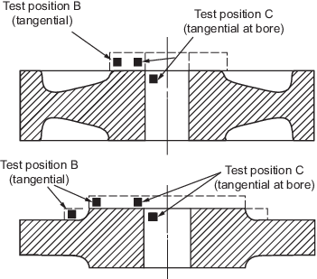
Figure 5.6.2 Test positions for turbine disc
forgings
6.6 Non-destructive examination
6.6.1 The end faces
of the body of rotor forgings and the end faces of the boss and the
bore surface of each turbine disc are to be machined to a fine smooth
finish for visual and magnetic particle examination.
6.6.2 The manufacturer
is to carry out an ultrasonic examination of each forging and is to
provide the Surveyor with a signed statement that such inspection
has not revealed any significant internal defects.
6.6.3 Rotor forgings
for propulsion machinery and for auxiliary turbines exceeding 1100
kW are to be hollow bored for internal examination. The surface of
the bore is to have a fine smooth finish and is to be examined by
means of an optical instrument of suitable magnification. Where the
bore size permits, magnetic particle examination is also to be carried
out. These examinations are to be confirmed by the Surveyor. Alternatively,
an approved method of ultrasonic examination may be accepted instead
of hollow boring. Details of the proposed method of ultrasonic examination
are to be submitted for special consideration.
Table 5.6.1 Mechanical properties for
acceptance purposes: carbon-manganese steel forgings for turbines - Normalised and
tempered
| Tensile strength
N/mm2
|
Yield stress
N/mm2 minimum
|
Elongation 5,65 % minimum % minimum
|
Reduction of area % minimum
|
| A
|
B
|
C
|
A
|
B
|
C
|
| 400 – 520
|
200
|
26
|
22
|
18
|
50
|
40
|
35
|
| 440 – 560
|
220
|
24
|
21
|
17
|
50
|
40
|
35
|
| 480 – 600
|
240
|
22
|
19
|
15
|
45
|
35
|
30
|
| 520 – 640
|
260
|
21
|
18
|
14
|
45
|
35
|
30
|
| 560 – 680
|
280
|
20
|
17
|
13
|
40
|
30
|
25
|
| 600 – 720
|
300
|
18
|
15
|
12
|
40
|
30
|
25
|
Columns A are applicable to longitudinal tests from rotor and spindle
forgings.
Columns B are applicable to tangential tests from
rotor forgings.
Columns C are applicable to radial tests from
rotor forgings.
Intermediate values may be obtained by
interpolation.
|
6.7 Thermal stability tests
6.7.1 Thermal stability
tests after heat treatment and rough machining of the turbine rotors,
referred to in the relevant Rules dealing with design and construction,
are to be undertaken in properly constructed furnaces, using accurate
and reliable measuring equipment. Each test is to be carried out in
accordance with the following recommended procedure:
-
Five bands are to be
machined concentric with the axis of rotation. Two of these are to
be reference bands and are to be positioned at or near the locations
of the bearings. The remaining three bands are to be test bands located
one as near as possible to the mid-length, and the other two near
each end of the body. Where the length of a rotor is such that five
bands cannot be provided, alternative proposals are to be submitted
to the Surveyor for his approval.
-
Four positions, 90°
apart, are to be stamped A, B, C and D on the coupling end of the
rotor.
-
The whole of the body,
and as much of the shaft at either end as will include the positions
of the glands, is to be enclosed in the furnace. In the case of a
rotor having an overhung astern wheel, the astern wheel is also to
be enclosed in the furnace during the first test.
-
The rotor is to be
rotated at a uniform and very low speed.
-
The deflections at
all bands are to be recorded at the A, B, C and D positions. Initial
cold readings are to be taken prior to heating.
-
The rotor is to be
heated uniformly and slowly. Temperatures are to be recorded continuously
at the surface of the rotor and, if practicable, in the bore at the
mid-length of the body. In no circumstances is the surface temperature
to exceed the temperature at which the rotor was tempered. During
heating, the rate of rise of temperature is to be such as to avoid
excessive temperature gradients in the rotor.
-
The maximum or holding
temperature is to be not less than 28°C above the maximum operating
temperature of the rotor. For the purposes of the test, the holding
period is to start when the rotor has attained a uniform and specified
temperature. The rotor is to be held under the specified temperature
conditions until not less than three consecutive hourly readings of
deflections show the radial eccentricity to be constant within 0,006
mm on all test bands.
-
The turbine rotor is
to be rotated during cooling until the temperature is not more than
100°C. The rate of cooling is to be such as to avoid excessive
temperature gradients in the rotor.
-
Final cold readings
are to be taken.
Table 5.6.2 Mechanical properties for
acceptance purposes: alloy steel forgings for turbines - Quenched and tempered or
normalised and tempered
| Tensile strength
N/mm2 (see Note)
|
Yield stress
N/mm2 minimum Normalised and tempered
|
Yield stress
N/mm2 minimum Quenched and tempered
|
Elongation on 5,65 % minimum % minimum
|
Reduction of area % minimum
|
| A
|
B
|
C
|
A
|
B
|
C
|
| 500 –
650
|
275
|
–
|
22
|
20
|
18
|
50
|
40
|
35
|
| 550 –
700
|
300
|
–
|
20
|
18
|
16
|
50
|
40
|
35
|
| 600 –
750
|
330
|
410
|
18
|
16
|
14
|
50
|
40
|
35
|
| 650 –
800
|
355
|
450
|
17
|
15
|
13
|
50
|
40
|
35
|
|
|
|
|
|
|
|
|
|
|
| 700 –
850
|
385
|
490
|
16
|
14
|
12
|
45
|
35
|
30
|
| 750 –
900
|
–
|
530
|
15
|
13
|
11
|
45
|
35
|
30
|
| 800 –
950
|
–
|
590
|
14
|
12
|
10
|
45
|
35
|
30
|
| 850 –
1000
|
–
|
640
|
13
|
11
|
9
|
40
|
30
|
25
|
|
|
|
|
|
|
|
|
|
|
| 900 –
1050
|
–
|
690
|
13
|
11
|
9
|
40
|
30
|
25
|
| 950 –
1100
|
–
|
750
|
12
|
10
|
8
|
40
|
30
|
25
|
| 1000 –
1150
|
–
|
810
|
12
|
10
|
8
|
40
|
30
|
25
|
Columns A are applicable to longitudinal tests from rotor and spindle
forgings.
Columns B are applicable to tangential tests from
rotor and spindle forgings, and to tangential tests from discs – test
position B in Figure 5.6.2 Test positions for turbine disc
forgings.
Columns C are
applicable to radial test from rotor forgings and to tangential tests from
discs – test position C in Figure 5.6.2 Test positions for turbine disc
forgings.
Intermediate values
may be obtained by interpolation.
|
6.7.2 The movements
of the axis of the rotor in relation to the reference bands are to
be determined from polar plots of the deflection readings. The radial
movement of the shaft axis, as determined by the difference between
the final hot and the final cold movements, is not to exceed 0,025
mm on any one band. As verification that test equipment and conditions
are satisfactory, it is required that similar determinations of differences
between initial cold and final cold movements do not exceed 0,025
mm on any one band.
6.7.3 If the results
of the test on a rotor fail to meet either or both of the requirements
in Ch 5, 6.7 Thermal stability tests 6.7.2, the test may be repeated
if requested by the maker and agreed by the Surveyor. In the case
of a rotor failing to meet the requirements of a thermal stability
test, the rotor is deemed unacceptable. Proposals for the rectification
of thermal instability of a rough machined rotor are to be submitted
for special consideration.
|