
Section
10 Bulkheads
10.1 General
10.1.1 The requirements of Pt 4, Ch 1, 9 Bulkheads are to be applied, together with the requirements of this
Section.
10.1.4 All bulk carriers to be classed ‘100A1 bulk carrier, strengthened for
heavy cargoes, any hold may be empty, ESP’ are to be arranged with top and bottom
stools. The requirements of Pt 4, Ch 7, 10.2 Bulkheads supported by stools are to be complied with as appropriate.
10.1.5 For self-unloading bulk carriers, the conveyor space is to be maintained watertight at
the transverse watertight bulkheads, i.e. watertight gates are to be fitted. The gates
are to be of equivalent strength to the unpierced bulkhead, prototype tested, and hose
tested in place in accordance with Pt 3, Ch 1, 9 Procedures for testing tanks and tight boundaries.
Alternative equivalent arrangements will be specially considered.
10.2 Bulkheads supported by stools
10.2.1 The
stools are to be reinforced with plate diaphragms or deep webs, and
in bottom stools the diaphragms are to be aligned with double bottom
side girders. Continuity is also to be maintained between the diaphragms
and the bulkhead corrugations for 90° corrugations.
10.2.2 The sloping plate of bottom stools is to be aligned with double bottom
floors. Particular attention is to be given to the through thickness properties of the
inner bottom plating and continuity at the connection to the inner bottom, and to the
through thickness properties of the bottom stool shelf plate, see
Ch 3, 8 Plates with specified through thickness properties of the Rules for the Manufacture, Testing and Certification
of Materials regarding requirements for plates with specified through thickness
properties.
10.2.3 An
efficient system of reinforcement is to be arranged in line with the
hold transverse bulkheads or bulkhead stools at the intersection with
the sloped plating of the hopper and topside tanks. The reinforcement
fitted in the tanks is to consist of girders or intercostal bulb plate
or equivalent stiffeners fitted between, and connected to, the sloped
bulkhead longitudinals.
10.2.4 The
shelf plates of the bulkhead stools are to be arranged to align with
the longitudinals in the hopper and topside tanks. Where sloping shelf
plates are fitted to stools, suitable scarfing is to be arranged in
way of the connections of the stools to the adjoining structures.
10.2.5 The ShipRight FDA Procedure, Structural Detail Design Guide (SDDG),
indicates recommended structural design configurations in the critical
areas of the lower stool and of the upper boundaries.
10.3 Structural details in way of holds confined to dry cargoes
10.3.1 In
dry cargo holds where transverse bulkheads are arranged without bottom
stools, the stiffeners and brackets of plane bulkheads, and rectangular
corrugations of corrugated bulkheads, are to be aligned with floors
and inner bottom longitudinals. In the case of non-rectangular corrugations,
the flanges are to be aligned with floors, but consideration will
be given to the fitting of a substantial transverse girder in place
of one of the floors.
10.3.2 Where
transverse corrugated bulkheads are arranged without top stools, transverse
beams are to be arranged under the deck in way.
10.4 Vertically corrugated transverse watertight bulkheads –
Application and definitions
10.4.1 Where
corrugated transverse watertight bulkheads are fitted, the scantlings
are to be determined in accordance with the following requirements.
10.4.3 The
loads to be considered as acting on the bulkheads are those given
by the combination of cargo loads with those induced by the flooding
of one hold adjacent to the bulkhead under consideration. The most
severe combinations of cargo induced loads and flooding loads are
to be used for the determination of the scantlings of each bulkhead,
depending on the specified design loading conditions:
-
homogeneous loading conditions;
-
non-homogeneous loading conditions (excluding part loading conditions
associated with multi-port loading and unloading); and
-
packed cargo
conditions (such as steel mill products).
The individual flooding of loaded and empty holds is to be considered, but
the pressure used in the assessment is not to be less than that obtained for flood water
alone. Holds containing packed cargo are to be treated as empty holds. For
self-unloading bulk carriers where the boundary of the conveyor space between the bottom
of the cargo hold and the top of the conveyor space is not watertight during seagoing
operations, the loads acting on the bulkheads are to be considered using the extent to
which flooding can occur, i.e. both the conveyor space and the cargo hold are to be
assumed to be flooded.
10.4.4 The
cargo surface is to be taken as horizontal and at a distance d
1, in metres, from the base line, see
Figure 7.10.1 Cargo hold dimensions, where d
1 is calculated taking into account the cargo properties and
the hold dimensions. Unless the ship is designed to carry only cargo
of bulk density greater than or equal to 1,78 tonne/m3 in
non-homogeneous loading conditions, the maximum mass of cargo which
may be carried in the hold is to be taken as filling that hold to
the upper deck level at centreline. A permeability, μ, of 0,3 and
angle of repose, ψ, of 35° is to be assumed for this application.
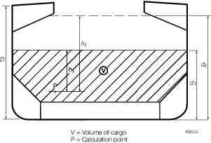
Figure 7.10.1 Cargo hold dimensions
10.4.5 An
homogeneous load condition is defined as one where the ratio between
the highest and the lowest filling levels, d
1,
in adjacent holds does not exceed 1,20. For this purpose, where a
loading condition includes cargoes of different densities, equivalent
filling levels are to be calculated for all holds on the basis of
a single reference value of cargo density, which can be the minimum
to be carried.
10.4.6 The
permeability, μ, may be taken as 0,3 for ore, coal and cement cargoes.
The bulk density and angle of repose, ψ, may generally be taken
as 3,0 tonne/m3 and 35° respectively for iron ore and
1,3 tonne/m3 and 25° respectively for cement.
10.4.7 The
flooding head, h
f, see
Figure 7.10.1 Cargo hold dimensions, is the distance, in
metres, measured vertically with the ship in the upright position,
from the location P, under consideration, to a position d
f, in metres, from the base line as given in Table 7.10.1 Flooding head.
10.4.8 In
considering a flooded hold, the total load is to be taken as that
of the cargo and flood water at the appropriate permeability. Where
there is empty volume above the top of the cargo, this is to be taken
as flooded to the level of the flooding head.
10.4.10 The
term net plate thickness is used to describe the calculated minimum
thickness of plating of the web, t
w, or flange, t
f. The plate thickness to be fitted is the net
plate thickness plus a corrosion addition of 3,5 mm.
10.5 Vertically corrugated transverse watertight bulkheads –
Scantling assessment
10.5.1 The bending moment M, in kNm, for the bulkhead corrugations is given
by:
where

|
= |
span of the corrugation,
in metres, to be measured between the internal ends of the bulkhead
upper and lower stools in way of the neutral axis of the corrugations
or, where no stools are fitted, from inner bottom to deck, see
Figure 7.10.2 Dimensions of bulkhead corrugation angles and Figure 7.10.3 Scantling assessment. The lower end of the
upper stool is not to be taken greater than a distance from the deck
at the centreline equal to:
|
| = |
3 times the depth of the corrugation, in general, or |
| = |
2 times the depth of the corrugation, for rectangular stools |
|
F
|
= |
resultant force, in kN, see
Table 7.10.3 Resultant pressure and
force. |

Figure 7.10.2 Dimensions of bulkhead corrugation angles
10.5.2 The shear force, Q, in kN at the lower end of the bulkhead
corrugation is given by:
where F is defined in Pt 4, Ch 7, 10.5 Vertically corrugated transverse watertight bulkheads – Scantling assessment 10.5.1.
Table 7.10.1 Flooding head
| Item
|
Bulkhead location
|
Bulk carriers with
|
Other bulk carriers
|
| Type B freeboard and
|
| deadweight < 50 000 tonnes
|
|
I
(1)
|
Between holds 1 and 2
|
|
|
|
|
Elsewhere
|
|
|
|
II
(1)
|
Between holds 1 and 2
|
|
|
|
|
Elsewhere
|
|
|
Note
1. Item II is to be used for
non-homogeneous loading conditions where the bulk cargo density is
less than 1,78 tonne/m3.
Otherwise, Item I is to be used.
Note
2.
D = distance, in metres, from the base line to the freeboard
deck at side amidships, see Fig 7.10.1.
|
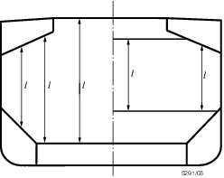
Figure 7.10.3 Scantling assessment
10.5.3 The
section modulus of the corrugations is to be calculated using net
plate thicknesses. At the lower end, the following requirements apply:
-
An effective
width of compression flange, b
ef, not greater
than given in Pt 4, Ch 7, 10.5 Vertically corrugated transverse watertight bulkheads – Scantling assessment 10.5.7, is
to be used.
-
Where corrugation
webs are not supported by local brackets below the shelf plate (or
below the inner bottom if no lower stool is fitted), they are to be
assumed 30 per cent effective in bending. Otherwise, the full area
of web plates may be used, see also
Pt 4, Ch 7, 10.5 Vertically corrugated transverse watertight bulkheads – Scantling assessment 10.5.3.(e).
-
Where effective
shedder plates are fitted, see
Figure 7.10.4 Symmetric shedder plates and Figure 7.10.5 Asymmetric shedder plates, the net area of the
corrugation flange plates, in cm2, may be increased by
the lesser of:
A shedder plate is considered effective when it:
- is not knuckled; and
- is welded to the corrugations and the lower stool shelf plate
by one-side penetration welds or equivalent; and
- has a minimum slope of 45° and lower edges in line with the
stool side plating; and
- has a thickness not less than 0,75 times the thickness of the
corrugation flanges; and
- has material properties at least equal to those of the corrugation
flanges.
-
Where effective
gusset plates are fitted, see
Figure 7.10.6 Symmetric gusset/shedder plates and Figure 7.10.7 Asymmetric gusset/shedder plates the net area of the corrugation
flange plates, in cm2, may be increased by:
- where
|
h
g
|
= |
height of the gusset plate, in metres, but is not to be taken
greater than 
|
|
t
f
|
= |
net flange plate thickness, in mm |
|
s
gu
|
= |
width of the gusset plate, in metres |
A gusset plate is considered effective when it:
- is fitted in combination with an effective shedder plate as defined
in Pt 4, Ch 7, 10.5 Vertically corrugated transverse watertight bulkheads – Scantling assessment 10.5.3.(c); and
- has height not less than half the flange plate width; and
- is fitted in line with the stool side plating; and
- has thickness and material properties at least equal to those
of the flanges; and
- is welded to the top of the lower stool by full penetration welds
and to the corrugations and shedder plates by one-side penetration
welds or equivalent.
-
Where the corrugation
is welded to a sloping stool shelf plate, set at an angle of not less
than 45° to the horizontal, the corrugation webs may be taken
as fully effective in bending. Where the slope is less than 45°,
the effectiveness is to be assessed by linear interpolation between
fully effective at 45° and the appropriate value from Pt 4, Ch 7, 10.5 Vertically corrugated transverse watertight bulkheads – Scantling assessment 10.5.3.(b) at 0°. Where effective
gusset plates are also fitted, the area of the flange plates may be
increased in accordance with Pt 4, Ch 7, 10.5 Vertically corrugated transverse watertight bulkheads – Scantling assessment 10.5.3.(d).
No increase is permitted in the case where shedder plates are fitted
without gussets.
Table 7.10.2 Bulkhead pressure and
force
| Item
|
Pressure, kN/m2
(tonne-f/m2)
|
Force, kN (tonne-f)
|
| (1) In non-flooded bulk cargo
holds
|
p
c = g ρc
h
1 tan2
θ
|
F
c = 0,5ρc
g
s
1(d
1–h
DB–h
LS)2 tan2
θ
|
|
|
(p
c = ρc
h
1 tan2
θ)
|
(F
c = 0,5ρc
s
1(d
1–h
DB–h
LS)2 tan2
θ)
|
|
(2) In flooded bulk cargo holds, when d
f ≥ d
1
|
|
F
cf = 0,5s
1(ρg(d
f–d
1)2+(ρg(d
f–d
1)+p
l
e)(d
1–h
DB–h
LS))
|
|
(a) For positions between d
1 and d
f from base line
|
p
cf = gρh
f
|
|
|
(p
cf = ρh
f)
|
|
(b) For positions at a distance lower than d
f from base line
|
p
cf = g (ρ h
f + ( ρc – ρ (1–μ))h
1 tan2
θ
|
(F
cf = 0,5s
1(ρ(d
f–d
1)2+(ρ(d
f–d
1)+p
l
e)(d
1–h
DB–h
LS)))
|
|
|
(p
cf = (ρ h
f + ( ρc – ρ (1–μ))h
1 tan2
θ)
|
| (3) In flooded bulk cargo holds, when
d
f < d
1
|
|
F
cf = 0,5s
1(ρc
g(d
1 – d
f)2tan2
θ+(ρc
g(d
1–
d
f)tan2
θ+p
le)(d
f–h
DB–h
LS))
|
| (a) For positions between d
1 and d
f from base line
|
p
cf = g ρc
h
1 tan2
θ
|
|
|
(p
cf = ρc
h
1 tan2
θ)
|
| (b) For positions at a distance lower
than d
f from base line
|
p
cf = g(ρh
f+( ρc
h
1–ρ(1–μ)h
f)tan2
θ)
|
(F
cf = 0,5s
1(ρc(d
1–d
f)2tan2
θ+(ρc(d
1–
d
f)tan2
θ+p
le)(d
f–h
DB–h
LS)))
|
|
|
(p
cf = (ρh
f+( ρc
h
1–ρ(1–μ)h
f)tan2
θ))
|
| (4) In flooded empty holds
|
p
f = gρh
f
|
F
f = 0,5s
1ρg(d
f–h
DB–h
LS)2
|
|
|
(p
f = ρh
f)
|
(F
f = 0,5s
1ρ(d
f–h
DB–h
LS)2)
|
| Symbols
|
d
f
see
Pt 4, Ch 7, 10.4 Vertically corrugated transverse watertight bulkheads – Application and definitions 10.4.7
|
g
|
= |
gravitational constant, 9,81 m/sec2
|
|
h
DB
|
= |
height of double bottom, in metres |
|
h
LS
|
= |
mean height of lower stool, in metres |
|
pc, pcf, pf
|
= |
pressure on the bulkhead at the point under
consideration, in kN/m2
|
|
p
l
e
|
= |
pressure at the lower end of the corrugation, in
kN/m2
|
|
ρ |
= |
density of sea water = 1,025 tonne/m3
|
|
ρc
|
= |
bulk cargo density, in tonne/m3
|
|
ψ |
= |
angle of repose of the cargo, in degrees |
|
Table 7.10.3 Resultant pressure and
force
| Loading condition
|
Resultant
pressure
kN/m2
|
Resultant
force
kN
|
| Homogeneous
|
p
r = p
cf–0,8p
c
|
F = F
cf–0,8F
c
|
| Non-homogeneous
|
p
r = p
cf
|
F = F
cf
|
| Flood water alone
(adjacent holds empty)
|
p
r = p
f
|
F = F
f
|
|
NOTE
For symbols, see Table 7.10.2.
|
10.5.5 The
bending capacity of the bulkhead corrugations is to comply with the
following relationship:
where
|
M
|
= |
bending moment, in kNm, see
Pt 4, Ch 7, 10.5 Vertically corrugated transverse watertight bulkheads – Scantling assessment 10.5.1
|
|
Z
le
|
= |
section modulus at the lower end of the corrugations, in cm3
|
|
Z
m
|
= |
section modulus at mid-span of the corrugations, in cm3
|
|
σp,le
|
= |
permissible bending stress at the lower end of the corrugations, in
N/mm2 |
|
σp,m
|
= |
permissible bending stress at mid-span of the corrugations, in
N/mm2
|
In the above expression Z
le, in cm3,
is not to be taken greater than Z'le where
and Z
m is not to exceed the
lesser of 1,15Z
leand 1,15Z'le
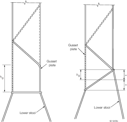
Figure 7.10.7 Asymmetric gusset/shedder plates
10.5.6 The applied shear stress, in N/mm2, is determined by dividing the
shear force derived from Pt 4, Ch 7, 10.5 Vertically corrugated transverse watertight bulkheads – Scantling assessment 10.5.2 by the shear area of the corrugation, calculated
using the net plate thickness. The shear area is to be reduced to account for non-
perpendicularity between the corrugation webs and flanges. In general, the reduced area
may be obtained by multiplying the web sectional area by sin φ, where φ is the angle
between the web and the flange, see
Figure 7.10.2 Dimensions of bulkhead corrugation angles. The applied shear stress is not to exceed the
permissible shear stress or the shear buckling stress given in Table 7.10.4 Permissible shear and buckling
stresses.
Table 7.10.4 Permissible shear and buckling
stresses
| Bending,
|
Shear,
|
Shear
buckling,
|
| N/mm2
|
N/mm2
|
N/mm2
|
| σp =
σ0
|
τp = 0,5σ0
|
|
| Symbols
|
|
t
f
|
= |
net flange plate thickness, in mm |
|
t
w
|
= |
web plate net thickness, in mm |
|
E
|
= |
modulus of elasticity |
| = |
206 000 N/mm2
|
|
σ
0
|
= |
specified minimum yield stress, in N/mm2
|
|
τE
|
= |
5,706 E (t
w/1000c)2 N/mm2
|
|
τ0
|
= |
 N/mm2 N/mm2
|
|
10.5.8 The
corrugation flange and web local net plate thickness are not to be
less than:
where
|
s
w
|
= |
plate width, in metres, to be taken equal to the width of the
corrugation flange or web, whichever is the greater |
|
p
r
|
= |
resultant pressure, in kN/m2, as defined in Table 7.10.3 Resultant pressure and
force, at the lower edge of each strake of
plating. The net thickness of the lowest strake is to be determined using the
resultant pressure at the top of the lower stool, (or at the inner bottom, if no
lower stool is fitted), or at the top of the shedders, if effective shedder or
gusset and shedder plates are fitted |
|
σ0
|
= |
specified minimum yield stress of the material, in N/mm2. |
10.5.9 For built-up corrugations, where the thickness of the flange and of the web
are different, the net thickness of the narrower plating is to be not less than:
where
|
s
n
|
= |
width of the narrower plating, in metres. |
The net thickness, in mm, of the wider plating is not to be taken less than
the greater of:
where
t
np ≤ actual net thickness of the narrower plating but not greater
than:
10.5.11 Scantlings
required to meet the bending and shear strength requirements at the
lower end of the bulkhead corrugation are to be maintained for a distance
of 0,15l from the lower end, where l is
as defined in Pt 4, Ch 7, 10.5 Vertically corrugated transverse watertight bulkheads – Scantling assessment 10.5.1. Scantlings
required to meet the bending requirements at mid-height are to be
maintained to a location no greater than 0,3l from the
top of the corrugation. The section modulus of the remaining upper
part of the corrugation is to be not less than 0,75 times that required
for the middle part, corrected for differences in yield stress.
10.6 Vertically corrugated transverse bulkheads – Support structure
at ends
10.6.2
Lower
stool:
-
The height of
the lower stool is generally to be not less than three times the depth
of the corrugations.
-
The thickness
and steel grade of the stool shelf plate are to be not less than those
required for the bulkhead plating above.
-
The thickness
and steel grade of the upper portion of vertical or sloping stool
side plating, within the depth equal to the corrugation flange width
from the stool top, are to be not less than the flange plate thickness
and steel grade needed to meet the bulkhead requirements at the lower
end of the corrugation.
-
The thickness of the stool side plating and the section modulus of
the stool side stiffeners are to be not less than those required by Pt 4, Ch 1, 9 Bulkheads for a plane transverse bulkhead and stiffeners using the
greater of the pressures determined from the head, h
4, in Table 1.9.1 Watertight and deep tank bulkhead
scantlings and the expressions given
in Table 7.10.2 Bulkhead pressure and
force.
-
The ends of stool
side vertical stiffeners are to be attached to brackets at the upper
and lower ends of the stool.
-
The width of
the shelf plate is to be in accordance with Figure 7.10.8 Width of shelf plate.
-
The stool bottom
is to have a width not less than 2,5 times the mean depth of the corrugation.
-
Scallops in the
brackets and diaphragms in way of connections to the stool shelf plate
are to be avoided.
-
Where corrugations
are terminated on the bottom stool, corrugations are to be connected
to the stool top plate by full penetration welds. The stool side plating
is to be connected to the stool top plate and the inner bottom plating
by either full penetration or partial penetration welds, see
Figure 7.10.9 Partial penetration welding. The supporting floors
are to be connected to the inner bottom by either full penetration
or partial penetration welds.

Figure 7.10.8 Width of shelf plate
10.6.3
Upper
stool:
-
The upper stool,
where fitted, is to have a height generally between two and three
times the depth of corrugations.
-
Rectangular stools
are to have a height generally equal to twice the depth of corrugations,
measured from the deck level and at hatch side girder.
-
The upper stool
is to be properly supported by girders or deep brackets between the
adjacent hatch-end beams.
-
The width of
the shelf plate is generally to be the same as that of the lower stool
shelf plate.
-
The upper end
of a non-rectangular stool is to have a width not less than twice
the depth of corrugations.
-
The thickness
and steel grade of the shelf plate are to be the same as those of
the bulkhead plating below.
-
The thickness
of the lower portion of stool side plating is to be not less than
80 per cent of that required for the upper part of the bulkhead plating
where the same materials are used.
-
The thickness of the stool side plating and the section modulus of the
stool side stiffeners are to be not less than those required by Ch 1,9 for plane
transverse bulkheads and stiffeners using the greater of the pressures determined
from the head, h
4, in Table 1.9.1 Watertight and deep tank bulkhead
scantlings and the expressions given
in Table 7.10.2 Bulkhead pressure and
force.
-
Where vertical
stiffening is fitted, the ends of stool side stiffeners are to be
attached to brackets at the upper and lower end of the stool.
-
Diaphragms are
to be fitted inside the stool, in line with, and effectively attached
to, longitudinal deck girders extending to the hatch end coaming girders
for effective support of the corrugated bulkhead.
-
Scallops in the
brackets and diaphragms in way of the connection to the stool shelf
plate are to be avoided.
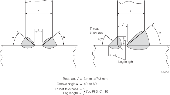
Figure 7.10.9 Partial penetration welding
10.6.4 If
no upper stool is fitted, two transverse reinforced beams are to be
fitted in line with the corrugation flanges.
10.6.5 If
no bottom stool is fitted, the corrugation flanges are to be in line
with the supporting floors. Corrugations are to be connected to the
inner bottom plating by full penetration welds. The thickness and
steel grades of the supporting floors are to be at least equal to
those provided for the corrugation flanges. The plating of supporting
floors is to be connected to the inner bottom by either full penetration
or deep penetration welds, see
Figure 7.10.9 Partial penetration welding. The cut-outs for connections
of the inner bottom longitudinals to double bottom floors are to be
closed by collar plates. The supporting floors are to be connected
to each other by suitably designed shear plates.
10.6.6 Stool
side plating is to align with the corrugation flanges. Stool side
vertical stiffeners and their brackets in the lower stool are to align
with the inner bottom longitudinals to provide appropriate load transmission
between these stiffening members. The lower stool side plating is
not to be knuckled.
10.6.7 The
design of local details is to take into account the transfer of the
bulkhead forces and moments to the boundary structures and particularly
to the double bottom and cross-deck structures.
10.7 Additional requirements for ships not built to the IACS Common Structural Rules
10.7.1 Bulk Carriers not built to the IACS Common Structural Rules are to comply with the
requirements of this sub-Section.
10.7.2 The safety factor with respect to lateral buckling of ordinary stiffeners on
transverse bulkheads and transverse bulkhead stools is to be 1,15 and calculated in
accordance with the ShipRight Guidance Notes for ShipRight SDA Buckling
Assessment.
|