
Section
2 Cylindrical shells and drums subject to internal pressure
2.1 Minimum thickness
2.1.3 Irrespective
of the thickness determined by the above formula, t is
to be not less than:
-
6,0 mm for cylindrical
shell plates.
-
For tube plates,
such thickness as will give a minimum parallel seat of 9,5 mm, or
such greater width as may be necessary to ensure tube tightness, see
Pt 5, Ch 10, 14.6 Fitting of tubes in water tube boilers.
2.2 Efficiency of ligaments between tube holes
2.2.1 Where
tube holes are drilled in a cylindrical shell in a line or lines parallel
to its axis, the efficiency, J, of the ligaments is to
be determined as in Pt 5, Ch 10, 2.2 Efficiency of ligaments between tube holes 2.2.2, Pt 5, Ch 10, 2.2 Efficiency of ligaments between tube holes 2.2.3 and Pt 5, Ch 10, 2.2 Efficiency of ligaments between tube holes 2.2.4.
2.2.7 For
spacing of tube holes on a diagonal line as shown in Figure 10.2.3 Spacing of holes on a diagonal line, or in a regular saw-tooth
pattern as shown in Figure 10.2.4 Regular saw-tooth patten of holes, J is to be determined from the formula in Pt 5, Ch 10, 2.2 Efficiency of ligaments between tube holes 2.2.8, where a and b, as shown in Figure 10.2.3 Spacing of holes on a diagonal line and Figure 10.2.4 Regular saw-tooth patten of holes, are measured, in mm, on
the median line of the plate, and d, is as defined in Pt 5, Ch 10, 2.2 Efficiency of ligaments between tube holes 2.2.2.
2.2.9 For
regularly staggered spacing of tube holes as shown in Figure 10.2.5 Regular staggering of holes, the smallest value
of the efficiency, J, of all ligaments (longitudinal,
circumferential and diagonal) is obtained from Figure 10.2.7 Compensation of welded tube stubsThe calculated
minimum thickness is to satisfy 7.1, where a and b, as shown in Figure 10.2.5 Regular staggering of holes,
are measured, in mm, on the median line of the plate, and d is
as defined in Pt 5, Ch 10, 2.2 Efficiency of ligaments between tube holes 2.2.2.
2.2.10 For
irregularly spaced tube holes whose centres do not lie on a straight
line, the formula in Pt 5, Ch 10, 2.2 Efficiency of ligaments between tube holes 2.2.3 is
to apply, except that an equivalent longitudinal width of the diagonal
ligament is to be used. An equivalent longitudinal width is that width
which gives, using the formula in Pt 5, Ch 10, 2.2 Efficiency of ligaments between tube holes 2.2.2, the same efficiency as would be obtained using the formula
in Pt 5, Ch 10, 2.2 Efficiency of ligaments between tube holes 2.2.8 for the diagonal
ligament in question.
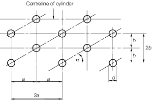
Figure 10.2.5 Regular staggering of holes
2.3 Compensating effect of tube stubs
2.3.1 Where
a drum or header is drilled for tube stubs fitted by strength welding,
either in line or in staggered formation, the effective diameter of
holes is to be taken as:
where
|
d
e
|
= |
the equivalent diameter of the hole, in mm |
|
d
a
|
= |
the actual diameter of the hole, in mm |
|
t
|
= |
the
thickness of the shell, in mm |
|
A
|
= |
the
compensating area provided by each tube stub and its welding fillets,
in mm2.
|
2.3.2 The
compensating area, A, is to be measured in a plane through
the axis of the tube stub parallel to the longitudinal axis of the
drum or header and is to be calculated as follows, see
Figure 10.2.7 Compensation of welded tube stubsThe calculated
minimum thickness is to satisfy 7.1 and Figure 10.2.8 Compensation of welded tube stubsThe calculated
minimum thickness is to satisfy 7.1:
- The cross-sectional area of the stub, in excess of that required
by Pt 5, Ch 10, 7.1 Minimum thickness for the minimum tube
thickness, from the interior surface of the shell up to a distance, b, from the outer surface of the shell;
- plus the cross-sectional area of the stub projecting inside the
shell within a distance, b, from the inner surface of
the shell;
- plus the cross-sectional area of the welding fillets inside and
outside the shell;
where
|
|
= |

|
|
t
b
|
= |
actual thickness of tube stub, in mm. |
2.4 Unreinforced openings
2.4.2 The
maximum diameter, d, of any unreinforced isolated openings
is to be determined by the following formula:
The value of K to be used is calculated
from the following formula:
2.4.3 For
elliptical or oval holes, d, for the purposes of Pt 5, Ch 10, 2.4 Unreinforced openings 2.4.2, refers to the major axis
when this lies longitudinally or to the mean of the major and minor
axes when the minor axis lies longitudinally.
2.4.4 No
unreinforced opening is to exceed 200 mm in diameter.
2.4.5 Holes
may be considered isolated if the centre distance between two holes
on the longitudinal axis of a cylindrical shell is not less than:
where
|
d
|
= |
diameter
of openings in shell (mean diameter if dissimilarly sized holes involved) |
|
D
|
= |
mean
diameter of shell |
|
t
|
= |
actual
thickness of shell |
Where the centre distance is less than so derived, the holes
are to be fully compensated.
Where two holes are offset
on a diagonal line, the diagonal efficiency from Figure 10.2.6 Efficiency of ligaments between holes may be used to derive
an equivalent longitudinal centre distance for the purposes of this
paragraph.
2.5 Reinforced openings
2.5.1 Openings
larger than those permitted by Pt 5, Ch 10, 2.4 Unreinforced openings are
to be compensated in accordance with Figure 10.2.9 Compensation for welded standpipes or branches in cylindrical shells(a) or (b). The following symbols are used in Figure 10.2.9 Compensation for welded standpipes or branches in cylindrical shells(a) and (b):
|
t
s
|
= |
calculated thickness of a shell without joint or opening or
corrosion allowance, in mm |
|
t
d
|
= |
thickness calculated in accordance with 7.1 without corrosion
allowance, in mm |
|
t
a
|
= |
actual thickness of shell plate without corrosion allowance,
in mm |
|
t
b
|
= |
actual thickness of standpipe without minus tolerances and corrosion
allowance, in mm |
|
t
r
|
= |
thickness of added reinforcement, in mm |
|
D
i
|
= |
internal diameter of cylindrical shell, in mm |
|
d
o
|
= |
diameter of hole in shell, in mm |
|
L
|
= |
width
of added reinforcement not exceeding D, in mm
|
|
C
|
= |
 in mm in mm
|
|
D
|
= |
 and is not to exceed 0,5d
o, in
mm and is not to exceed 0,5d
o, in
mm
|
|
σ |
= |
shell plate
allowable stress, N/mm2
|
|
σp
|
= |
standpipe
allowable stress, N/mm2
|
|
σr
|
= |
added
reinforcement allowable stress, N/mm2
|
|
σw
|
= |
weld
metal allowable stress, N/mm2
|
Note
|
σp, σr and σw
|
= |
are not to be taken as greater
than σ. |
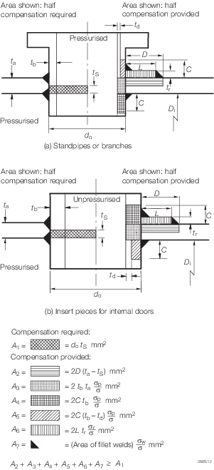
Figure 10.2.9 Compensation for welded standpipes or branches in cylindrical shells
2.5.3 Compensation
is to be distributed equally on either side of the centreline of the
opening.
2.5.4 The
welds attaching standpipes and reinforcing plates to the shell are
to be of sufficient size to transmit the full strength of the reinforcing
areas and all other loadings to which they may be subjected.
|