
Section
1 General
1.1 Application
1.1.1 The
requirements of this Chapter apply to the design and construction
of piping systems, including pipe fittings forming parts of such systems.
1.1.2 The
materials used for pipes, valves and fittings are to be suitable for
the medium and the service for which the piping is intended.
1.2 Definitions
1.2.1
Piping
system includes pipes and fittings such as expansion joints,
valves, pipe joints, support arrangements, flexible tube lengths,
etc. and components in direct connection with the piping such as pumps,
heat exchangers, air receivers, independent tanks, etc.
1.3 Design symbols
1.3.1 The
symbols used in this Chapter are defined as follows:
|
a
|
= |
percentage
negative manufacturing tolerance on thickness |
|
c
|
= |
corrosion
allowance, in mm |
|
pt
|
= |
hydraulic test pressure, in MPa |
|
t
|
= |
the
minimum thickness of a straight pipe, in mm, including corrosion allowance
and negative tolerance, where applicable |
|
t
b
|
= |
the minimum thickness of a straight pipe to be used for a pipe
bend, in mm, including bending allowance, corrosion allowance and
negative tolerance, where applicable |
|
R
|
= |
radius
of curvature of a pipe bend at the centreline of the pipe, in mm |
|
σ |
= |
maximum
permissible design stress, in N/mm2 (kgf/cm2).
|
1.3.2 The
outside diameter, D, is subject to manufacturing tolerances,
but these are not to be used in the evaluation of formulae.
1.3.3 The
inside diameter, d, is not to be confused with nominal
size, which is an accepted designation associated with outside diameters
of standard rolling sizes.
1.3.4 The
weld efficiency factor, e, is to be taken as 1 for seamless
and electric resistance and induction welded steel pipes. Where other
methods of pipe manufacture are proposed, the value of e will
be specially considered.
1.4 Design pressure
1.4.1 The
design pressure, p, is the maximum permissible working
pressure and is to be not less than the highest set pressure of the
safety valve or relief valve.
1.4.2 In
water tube boiler installations, the design pressure for steam piping
between the boiler and integral superheater outlet is to be taken
as the design pressure of the boiler, i.e. not less than the highest
set pressure of any safety valve on the boiler drum. For piping leading
from the superheater outlet, the design pressure is to be taken as
the highest set pressure of the superheater safety valves.
1.4.3 The
design pressure of feed piping and other piping on the discharge from
pumps is to be taken as the pump pressure at full rated speed against
a shut valve. Where a safety valve or other protective device is fitted
to restrict the pressure to a lower value than the shut valve load,
the design pressure is to be the highest set pressure of the device.
1.5 Design temperature
1.5.1 The
design temperature is to be taken as the maximum temperature of the
internal fluid, but in no case is it to be less than 50°C.
1.5.2 In
the case of pipes for superheated steam, the temperature is to be
taken as the designed operating steam temperature for the pipeline,
provided that the temperature at the superheater outlet is closely
controlled. Where temperature fluctuations exceeding 15°C above
the designed temperature are to be expected in normal service, the
steam temperature to be used for determining the allowable stress
is to be increased by the amount of this excess.
1.6 Classes of piping systems and
components
1.6.1 Pressure
piping systems are divided into three classes for the purpose of assigning
appropriate testing requirements, types of joints to be adopted, heat
treatment and weld procedure.
1.6.2 Dependent
on the service for which they are intended, Class II and III pipes
are not to be used for design pressure or temperature conditions in
excess of those shown in Table 12.1.1 Maximum pressure and temperature
conditions for Class II and III piping systems.
Where either the maximum design pressure or temperature exceeds that
applicable to Class II pipes, Class I pipes are to be used. To illustrate
this, see
Figure 12.1.1 Classes of piping system.
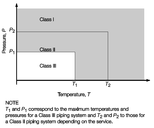
Figure 12.1.1 Classes of piping system
Table 12.1.1 Maximum pressure and temperature
conditions for Class II and III piping systems
| Piping system
|
Class II
|
Class III
|
|
|
P2
|
T2
|
P1
|
T1
|
|
|
MPa
|
°C
|
MPa
|
°C
|
| Steam
|
1,6
|
300
|
0,7
|
170
|
| Thermal oil
|
1,6
|
300
|
0,7
|
150
|
| Flammable Liquids, see Note 1
|
1,6
|
150
|
0,7
|
60
|
| Other media, see Note 2
|
4
|
300
|
1,6
|
200
|
| Cargo oil
|
4
|
300
|
1,6
|
200
|
Note
1. Flammable liquids include fuel oil,
lubricating oil and flammable hydraulic oil.
Note
2. Including water, air, gases,
non-flammable hydraulic oil.
|
1.6.4 Class II and III pipes are not to be used for toxic media.
1.6.5 Class I pipes are generally required for corrosive media. Class II pipes may be used for
corrosive media where special safeguards for reducing the potential for leakage and
limiting its consequences are provided, e.g. the use of pipe ducts, shielding,
screening, etc. in such a way that a leakage will not cause a potential hazard or damage
to surrounding areas. Class III pipes are not to be used for corrosive media. Materials
used for piping for corrosive media are to be specially considered.
1.7 Materials
1.7.3 The manufacturer's certificate for materials for ship-side valves and
fittings and valves on the collision bulkhead equal to or less than 500 mm nominal
diameter will be accepted in lieu of LR's materials certificate where the valves and
fittings are in accordance with a recognised National Standard applicable to the
intended application and are manufactured and tested in accordance with the appropriate
requirements of the Rules for the Manufacture, Testing and Certification of Materials, July 2022.
Table 12.1.2 Maximum conditions for pipes,
valves and fittings for which manufacturer's materials test certificate is
acceptable
| Material
|
DN = nominal diameter, mm
pw =
working pressure, MPa
|
| When the working
temperature is less than 300°C: Carbon and low alloy steel, austenitic
stainless steel and cast iron (spheroidal or nodular)
|
DN < 50
or
pw ×
DN < 250
|
| Copper alloy
intended for a working temperature of less than 200°C
|
DN < 50
or
pw ×
DN < 150
|
|