
Section
3 Design
3.1 Symbols
3.1.1 For
the purposes of this Chapter the following symbols apply:
|
a
|
= |
centre
distance, in mm |
|
d
|
= |
reference
diameter, in mm |
|
dan
|
= |
virtual tip diameter, in mm |
|
db
|
= |
base diameter, in mm |
|
dbn
|
= |
virtual base diameter, in mm |
|
den
|
= |
virtual diameter to the highest point of single tooth pair contact,
in mm |
|
df
|
= |
root diameter, in mm |
|
dfn
|
= |
virtual root diameter, in mm |
|
dn
|
= |
virtual reference diameter, in mm |
|
ds
|
= |
shrink diameter, in mm |
|
dw
|
= |
pitch circle diameter, in mm |
|
fma
|
= |
tooth flank misalignment due to manufacturing errors, in μm |
|
fpb
|
= |
maximum base pitch deviation of wheel, in μm |
|
fSh
|
= |
tooth flank misalignment due to wheel and pinion deflections,
in μm |
|
fSho
|
= |
intermediary factor for the determination of f
Sh
|
|
h
|
= |
total
depth of tooth, in mm |
|
hao
|
= |
basic rack addendum of tool, in mm |
|
hF
|
= |
bending moment arm for root stress, in mm |
|
hW
|
= |
sum of actual tooth addenda of pinion and wheel, in mm |
|
mn
|
= |
normal module, in mm |
|
q
|
= |
machining
allowances, in mm |
|
q'
|
= |
intermediary
factor for the determination of 
|
|
u
|
= |
gear ratio =  ≥ 1 ≥ 1 |
|
v
|
= |
linear
speed at pitch circle, in m/s |
|
x
|
= |
addendum
modification coefficient |
|
yα
|
= |
running in allowance, in μm |
|
yβ
|
= |
running in allowance, in μm |
|
zn
|
= |
virtual number of teeth |
| = |

|
|
Cγ
|
= |
tooth mesh stiffness (mean total mesh stiffness per unit face
width), in N/mm μm |
|
Ft
|
= |
nominal tangential tooth load, in N |
| = |
 19,098 x 106 19,098 x 106
|
|
Fβ
|
= |
total tooth alignment deviation (maximum value specified), in μm |
|
Fβx
|
= |
actual longitudinal tooth flank deviation before running in,
in μm |
|
Fβy
|
= |
actual longitudinal tooth flank deviation after running in,
in μm |
|
HV |
= |
Vickers hardness
number |
|
KFα
|
= |
transverse load distribution factor |
|
KFβ
|
= |
longitudinal load distribution factor |
|
KHα
|
= |
transverse load distribution factor |
|
KHβ
|
= |
longitudinal load distribution factor |
|
Kvα
|
= |
dynamic factor for spur gears |
|
Kvβ
|
= |
dynamic factor for helical gears |
|
P
|
= |
transmitted
power, in kW |
|
Pr
|
= |
radial pressure at shrinkage surface, in N/mm2
|
|
Pro
|
= |
protuberance of tool, in mm |
|
Ra
|
= |
surface roughness − arithmetical mean deviation (C.L.A.)
as determined by an instrument having a minimum wavelength cut-off
of 0,8 mm and for a sampling length of 2,5 mm, in μm |
|
Spr
|
= |
residual undercut left by protuberance in mm |
|
SF min
|
= |
minimum factor of safety for bending stress |
|
SFn
|
= |
tooth root chord in the critical section, in mm |
|
SH min
|
= |
minimum factor of safety for Hertzian contact stress |
|
SR
|
= |
rim thickness of gears, in mm |
|
YB
|
= |
rim thickness factor |
|
YR rel T
|
= |
relative surface finish factor |
|
YS
|
= |
stress correction factor |
|
YST
|
= |
stress correction factor (relevant to the dimensions of the
standard reference test gears) |
|
Yδ
rel T
|
= |
relative notch sensitivity factor |
|
ZE
|
= |
material elasticity factor |
|
ZR
|
= |
surface finish factor |

|
= |
contact ratio factor |
|
αen
|
= |
pressure
angle at the highest point of single tooth contact, in degrees |
|
αn
|
= |
normal
pressure angle at reference diameter, in degrees |
|
αt
|
= |
transverse
pressure angle at reference diameter, in degrees |
|
αtw
|
= |
transverse
pressure angle at pitch circle diameter, in degrees |
|
αF en
|
= |
angle for application of load at the highest point of single
tooth contact, in degrees |
|
β |
= |
helix angle
at reference diameter, in degrees |
|
βb
|
= |
helix
angle at base diameter, in degrees |
|
γ |
= |
intermediary
factor for the determination of f
Sh
|
 α
α
|
= |
transverse
contact ratio |
| = |

|
 αn
αn
|
= |
virtual
transverse contact ratio |
 β
β
|
= |
overlap
ratio |

|
= |
total contact ratio |
|
ρao
|
= |
tip
radius of tool, in mm |
|
ρc
|
= |
relative
radius of curvature at pitch point, in mm |
|
ρF
|
= |
tooth
root fillet radius at the contact of the 30° tangent, in mm |
|
σy
|
= |
yield
or 0,2 per cent proof stress, in N/mm2
|
|
σB
|
= |
ultimate
tensile strength, in N/mm2
|
|
σF
|
= |
bending
stress at tooth root, in N/mm2
|
|
σF lim
|
= |
endurance limit for bending stress in N/mm2
|
|
σFP
|
= |
allowable
bending stress at the tooth root, in N/mm2
|
|
σH
|
= |
Hertzian
contact stress at the pitch circle, in N/mm2
|
|
σH lim
|
= |
endurance limit for Hertzian contact stress, in N/mm2
|
|
σHP
|
= |
allowable
Hertzian contact stress, in N/mm2
|
Subscript:
3.2 Tooth form
3.2.1 The
tooth profile in the transverse section is to be of involute shape,
and the roots of the teeth are to be formed with smooth fillets of
radii not less than 0,25m
n.
3.2.2 All
sharp edges left on the tips and ends of pinion and wheel teeth after
hobbing and finishing are to be removed.
3.3 Tooth loading factors
3.3.1 For
values of application factor, K
A
see
Table 5.3.1 Values of K
A
.
Table 5.3.1 Values of K
A
| Main and auxiliary gears
|
K
A
|
| Main propulsion engine reduction gears:
|
|
|
|
Hydraulic coupling or equivalent on input
|
1,10
|
|
|
High elastic coupling on input
|
1,30
|
|
|
Other coupling
|
1,50
|
| Auxiliary gears:
|
|
|
|
Electric and engine drives with
hydraulic
coupling or equivalent on
input
|
1,00
|
|
|
Engine drives with high elastic coupling
on
input
|
1,20
|
|
|
Engine drives with other couplings
|
1,40
|
3.3.2 Load sharing factor, Kγ. When a gear drives two or more
mating gears where the total transmitted load is not evenly distributed between the
individual meshes, a factor, K
γ, is to be applied. K
γ is defined as the ratio between the maximum load through an actual path and
the evenly shared load. This is to be determined by measurements. Where a value cannot
be determined in such a way, the values in Table 5.3.2 Values of K
y
may be considered:
Table 5.3.2 Values of K
y
|
|
K
y
|
| Spur Gear
|
1,0
|
| Epicyclic Gears
|
|
|
|
1,0
|
|
|
1,2
|
|
|
1,3
|
- 6 planetary gears and over
|
1,4
|
3.3.3 Dynamic
factor, K
v, is to be calculated as follows
when all the following conditions are satisfied:
- spur gears (β = 0°) and helical gears with β ≤
30°
- pinion with relatively low number of teeth, z1 <
50
- solid disc wheels or heavy steel gear rim
Or this method may also be applied to all types of gears if:
And to helical gears where β > 30°
- For spur gears and for helical gears with ∊β ≥ 1:
Where K
A
F
t/b is less than 100 N/mm, the value 100 N/mm is to be used.
Numerical values for the factor K
1 are to be as specified in the Table 5.3.3 Values of K
1
.
Table 5.3.3 Values of K
1
|
|
K
1
ISO accuracy Grade
|
|
|
3
|
4
|
5
|
6
|
7
|
8
|
| Spur Gears
|
2,1
|
3,9
|
7,5
|
14,9
|
26,8
|
39,1
|
| Helical Gears
|
1,9
|
3,5
|
6,7
|
13,3
|
23,9
|
34,8
|
For all accuracy grades the factor K2 is to
be in accordance with the following:
- for spur gears K2 = 0,0193
- for helical gears K2 = 0,0087
Factor K
3 is to be in accordance with the following:
- For helical gears with overlap ratio ∊β < 1, the value
Kv is to be determined by linear interpolation between values
determined for spur gears (Kvα) and helical gears
(Kvβ) in accordance with:
K
v = Kvα – ∊ β (Kvα –
Kvβ )
K
vα is the Kv value for spur gears, in accordance with
(a)
K
vβ is the Kv value for helical gears, in accordance
with (b)
3.3.4 Longitudinal load distribution factors, KHβ and
KFβ:
Calculated values of KHβ > 2 are to be reduced by
improved accuracy and helix correction as necessary:
where
|
F
βy
|
= |
Fβx − yβ and |
|
Fβx
|
= |
1,33 fSh + fma
|
|
f
ma
|
= |
2/3 Fβ at the design stage, or |
|
f
ma
|
= |
1/3 Fβ where helix correction has been applied |
|
fSh
|
= |
 where where |
|
fSho
|
= |
23γ10−3 μm mm/N for gears without helix correction and
without end relief, or |
|
|
= |
16γ10−3 μm mm/N for gears without helix correction but
with end relief, where |
|
γ |
= |
 for single helical and spur gears for single helical and spur gears |
|
|
= |
 for double helical gears for double helical gears |
The following minimum values are applicable, these also being
the values where helix correction has been applied:
|
fSho
|
= |
10 x 10−3 μm mm/N for helical gears, or
|
|
|
= |
5 x 10⁻³ μm
mm/N for spur gears
|
For through-hardened steels and surface hardened
steels running on through-hardened steels:
For surface hardened steels, when
where
|
n |
= |

|
Note
1.
 is to be taken as the smaller of is to be taken as the smaller of 
Note
2. For double helical gears  is to be substituted for b in the equation
for n. is to be substituted for b in the equation
for n.
3.3.5 Transverse load distribution factors, KHα and
KFα
-
Values KHα and KFα for gears with total
contact ratio ∊γ ≤ 2
-
Values KHα and KFα for gears with
total contact ratio ∊γ > 2
Limiting conditions for KHα
If KHα > when calculated in accordance with (a) or (b), then
KHα = when calculated in accordance with (a) or (b), then
KHα = 
If KHα< 1 when calculated in accordance with (a)
or (b), then KHα= 1
Limiting conditions for KFα:
If KFα >  when calculated in accordance with (a) or (b), then K
Fα when calculated in accordance with (a) or (b), then K
Fα

If K
Fα< 1 when calculated in accordance with (a) or (b), then
KFα = 1
where
When tip relief is applied fpb is to be half of the
maximum specified value:
|
yα
|
= |
 for through-hardened steels, when for through-hardened steels, when |
- yα ≤
 μm and μm and
|
yα
|
= |
0,075 fpb for surface hardened steels, when |
When pinion and wheel are manufactured from different materials:
|
yα
|
= |

|
3.3.6 Tooth
mesh stiffness, C
γ:
|
Cγ
|
= |
 |
where
|
q'
|
= |

|
For internal gears z
n2 = ∞
Other calculations methods for C
γ will
be specially considered.
3.4 Tooth loading for surface stress
3.4.1 The Hertzian contact stress, σH, at the pitch circle is not to
exceed the allowable Hertzian contact stress, σHP.
where
|
ZH
|
= |

|
|
ZE
|
= |
189,8 for steel |
Z∊, contact ratio factor is to be calculated as follows:
for helical gears:
|
Z∊ |
= |
 for for  < 1 and < 1 and |
|
Z∊ |
= |
 for for  ≥ 1 ≥ 1 |
for spur gears:
|
Zβ
|
= |

|
|
ZR
|
= |

|
where
The peak-to-valley roughness determined for the pinion Rz1
and for the wheel R
z2 are mean values for the peak-to-valley roughness Rz
measured on several tooth flanks.
relative radius of curvature:
where:
For internal gears, db has a negative sign.
If Ra, the surface roughness of the tooth flanks is given
then the following approximation may be applied:
CZR is to be taken from Table 5.3.4 Values of CZR
.
For values of Zx, see
Table 5.3.5 Values of Zx
σH lim, see
Table 5.3.6 Values of endurance limit for
Hertzian contact stress, σH lim
S
H min, see
Table 5.3.7 Factors of safety.
Table 5.3.4 Values of CZR
| σH lim
|
C
ZR
|
| σHlim < 850 N/mm2
|
0,1500
|
| 850 N/mm2 ≤ σH lim ≤ 1200
N/mm2
|
= 0,32-0,0002 σHlim
|
| σHlim>1200
N/mm2
|
0,080
|
Table 5.3.5 Values of Zx
| Pinion heat treatment
|
Zx
|
| Carburised andinduction-hardened
|
- mn≤ 10
- 10 < mn < 30
- 30 ≤ m
n
|
|
| Nitrided
|
- m
n < 7,5
- 7,5 < mn < 30
- 30 ≤ mn
|
|
| Through- hardened
|
All modules
|
1,00
|
Table 5.3.6 Values of endurance limit for
Hertzian contact stress, σH lim
| Heat treatment
|
σH lim
N/mm2
|
| Pinion
|
Wheel
|
| Through-hardened
|
Through-hardened
|
0,46σB2 + 255
|
| Surface-hardened
|
Through-hardened
|
0,42σB2 + 415
|
| Carburised, nitrided
orinduction-hardened
|
Soft bath nitrided(Tufftrided)
|
1000
|
| Carburised, nitrided
orinduction-hardened
|
Induction-hardened
|
0,88 HV2 + 675
|
| Carburised ornitrided
|
Nitrided
|
1300
|
| Carburised
|
Carburised
|
1500
|
Table 5.3.7 Factors of safety
|
|
SH min
|
SF min
|
| Main propulsion gears
|
1,4
|
1,8
|
| Auxiliary gears
|
1,15
|
1,40
|
3.5 Tooth loading for bending stress
3.5.3 For
internal tooth forms the form factor is calculated, as an approximation,
for a substitute gear rack with the form of the basic rack in the
normal section, but having the same tooth depth as the internal gear:
where αF en is taken as being equal
to αn
d
en2 is calculated as d
en for external gears, and
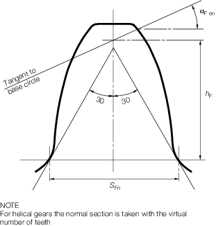
Figure 5.3.1 Normal tooth section
3.5.4 Stress concentration factor, Ys
where
|
L
|
= |

|
|
qs
|
= |

|
when qs< 1 the value of Ys is to be
specially considered.
The formula for Ys is applicable to external gears with
αn = 20° but may be used as an approximation for other pressure angles and
internal gears.
3.5.5 Helix angle factor Yβ
but Y
b ≥ 1 − 0,25 εb ≥ 0,75.
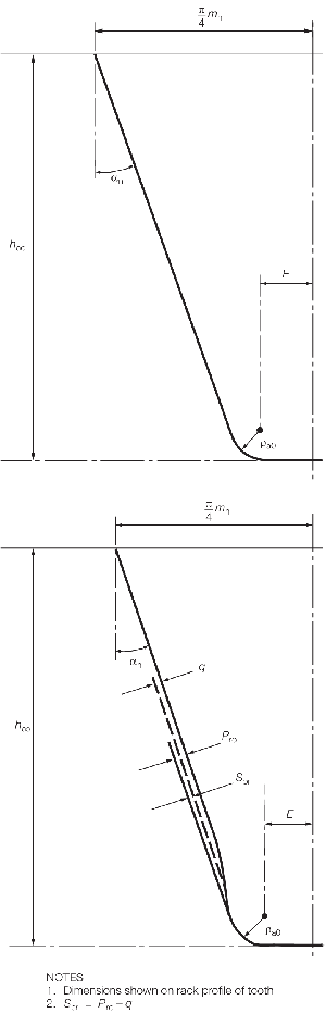
Figure 5.3.2 External tooth forms
3.5.6 Rim thickness factor, YB
Factor YB is to be determined as follows:
-
For external gears
If SR/h ≥ 1,2 then YB = 1
If 0,5 < SR/h <1,2 then
YB = 1,6∙ln
Where
SR = rim thickness of external gears, mm
The case SR/h ≤ 0,5 is to be avoided.
-
For internal gears
If SR/m
n ≥ 3,5 then YB = 1
If 1,75 < SR/mn <3,5 then
YB = 1,15∙ln
where
SR = rim thickness of internal gears, mm
The case SR /mn ≤ 1,75 is to be
avoided.
3.5.7 Deep tooth factor YDT
The deep tooth factor, YDT, adjusts the root stress to
take into account high precision gears and contact ratios within the range of virtual
contact ratio 2,05 ≤ ∊αn ≤ 2,05 where:
Factor YDT is to be determined from Table 5.3.9 Values of deep tooth factor,
Y
DT
:
Table 5.3.9 Values of deep tooth factor,
Y
DT
|
|
Y
DT
|
| ISO Accuracy Grade ≤ 4 and ∊αn >
2,5
|
0,7
|
| ISO Accuracy Grade ≤ 4 and 2,05<
∊αn ≤ 2,5
|
2,366– 0,666⋅∊αn
|
| In all other cases
|
1,0
|
3.5.8 Relative notch sensitivity factor, Yδ rel T
ρ’ = slip-layer thickness is to be taken
from Table 5.3.10 Slip-layer thickness, ρ’
Table 5.3.10 Slip-layer thickness, ρ’
| Material
|
ρ’, (mm)
|
| Case-hardened
steels, flame or induction-hardened steels
|
0,0030
|
|
|
500 N/mm2
|
0,0281
|
| Through-hardened steels, yield point
R
e =
|
600 N/mm2
|
0,0194
|
|
|
800 N/mm2
|
0,0064
|
|
|
1000 N/mm2
|
0,0014
|
| Nitrided
steels
|
0,1005
|
| Note: The given
values of ρ’ can be interpolated for values of R
e not stated above
|
3.5.9 Relative surface finish factor, YR rel T
|
YR rel T
|
= |
1,674 − 0,529 (6Ra + 1)0,1for
through-hardened, carburised and induction hardened steels, and |
|
YR rel T
|
= |
4,299 − 3,259 (6R
a + 1)0,005for
nitrided steels.
|
3.5.10 Size
factor, Y
x
|
Yx
|
= |
1,03 − 0,006m
n for through hardened
steels
|
|
Yx
|
= |
1,05 − 0,01m
n for surface-hardened
steels
|
|
Yx
|
= |
0,80, when m
n ≥ 25.
|
3.5.11 Design factor, YD
|
YD
|
= |
0,83 for gears treated with a controlled shot peening process |
|
YD
|
= |
1,25 for shrunk on gears, or |
|
YD
|
= |
1 +  , otherwise , otherwise |
3.6 Factors of safety
3.7 Design of enclosed gear shafting
3.7.2 The diameter of the enclosed gear shafting adjacent to the pinion or wheel
is to be not less than the greater of db or dt,
where:
|
|
= |
where |
|
S
b
|
= |
45 + 0,24 (σu – 400) and
|
|
S
s
|
= |
42 + 0,09 (σu – 400)
|
|
L
|
= |
span
between shaft bearing centres, in mm |
|
α
n
|
= |
normal pressure angle at the gear reference diameter, in degrees |
|
β
|
= |
helix
angle at the gear reference diameter, in degrees |
|
d
w
|
= |
pitch circle diameter of the gear teeth, in mm |
|
σ
u
|
= |
specified minimum tensile strength of the shaft material, in
N/mm2.
|
Note
P in kW and R in rpm are as
defined in Pt 5, Ch 1, 3.3 Power ratings.
Numerical
value used for σu is not to exceed 800 N/mm2 for
gear and thrust shafts.
3.7.3 For
the purposes of the above it is assumed that the pinion or wheel is
mounted symmetrically spaced between bearings.
3.7.4 Outside a length equal to the required diameter at the pinion or wheel, the
diameter may be reduced, if applicable, to that required for dt.
3.7.5 For bevel gear shafts, where a bearing is located adjacent to the gear
section, the diameter of the shaft is be not less than dt. Where a
bearing is not located adjacent to the gear the diameter of the shaft will be specially
considered.
|