
Section
1 Plans and particulars
1.1 Details to be submitted
1.1.1 A plan,
in triplicate, of the propeller is to be submitted for approval, together
with the following particulars using the symbols shown:
-
Maximum blade
thickness of the expanded cylindrical section considered, T,
in mm.
-
Maximum shaft
power, see
Pt 5, Ch 1, 3.3 Power ratings, P, in kW (H, in shp).
-
Estimated ship
speed at design loaded draught in the free running condition at maximum
shaft power and corresponding revolutions per minute, see
Pt 5, Ch 7, 1.1 Details to be submitted 1.1.1.(b) and Pt 5, Ch 7, 1.1 Details to be submitted 1.1.1.(d).
-
Revolutions per
minute of the propeller at maximum power, R.
-
Propeller diameter, D, in metres.
-
Pitch at 25 per
cent radius (for solid propellers only), P
0,25,
in metres.
-
Pitch at 35 per
cent radius (for controllable pitch propellers only), P
0,35, in metres.
-
Pitch at 60 per
cent radius P
0,6, in metres.
-
Pitch at 70 per
cent radius P
0,7, in metres.
-
Length of blade
section of the expanded cylindrical section at 25 per cent radius
(for solid propellers only), L
0,25, in mm.
-
Length of blade
section of the expanded cylindrical section at 35 per cent radius
(for controllable pitch propellers only) L
0,35,
in mm.
-
Length of blade
section of the expanded cylindrical section at 60 per cent radius, L
0,6, in mm.
-
Rake at blade
tip measured at shaft axis (backward rake positive, forward rake negative), A, in mm.
-
Number of blades, N.
-
Developed area
ratio, B.
-
Material: type
and specified minimum tensile strength.
-
θs,
skew angle, in degrees, see
Figure 7.1.1 Definition of skew angle.
-
Connection of
propeller to shaft — details of fit, push-up, securing, etc.
1.1.2 For
propellers having a skew angle equal to or greater than 50°, in
addition to the particulars detailed in Pt 5, Ch 7, 1.1 Details to be submitted 1.1.1, details are to be submitted of:
-
Full blade section
details at each radial station defined for manufacture.
-
A detailed blade
stress computation supported by the following hydrodynamic data for
the ahead mean wake condition and when absorbing full power:
-
Radial distribution
of lift and drag coefficients, section inflow velocities and hydrodynamic
pitch angles.
-
Section pressure
distributions calculated by either an advised inviscid or viscous
procedure.
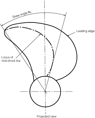
Figure 7.1.1 Definition of skew angle
1.1.3 For
blades of fixed pitch propellers with skew angle of  or greater, the stresses in the propeller blade during
astern operation are not to exceed 80 per cent of the propeller blade
material proof stress. Consideration is to be given to failure conditions
and a factor of safety of 1,5 is to be attained using an acceptable
fatigue failure criteria. Documentary evidence confirming that these
criteria are satisfied is to be submitted. or greater, the stresses in the propeller blade during
astern operation are not to exceed 80 per cent of the propeller blade
material proof stress. Consideration is to be given to failure conditions
and a factor of safety of 1,5 is to be attained using an acceptable
fatigue failure criteria. Documentary evidence confirming that these
criteria are satisfied is to be submitted.
1.1.4 The
maximum skew angle of a propeller blade is defined as the angle, in
projected view of the blade, between a line drawn through the blade
tip and the shaft centreline and a second line through the shaft centreline
which acts as a tangent to the locus of the mid-points of the helical
blade sections, see
Figure 7.1.1 Definition of skew angle.
1.1.5 Where
propellers and similar devices of unusual design are intended for
more than one operating regime, such as towing or trawling, then a
detailed blade stress calculation for each operating condition, indicating
the rotational and ship speed, is to be submitted for consideration.
1.1.6 Where
it is proposed to fit the propeller to the screwshaft without the
use of a key, plans of the boss, tapered end of screwshaft, propeller
nut and, where applicable, the sleeve, are to be submitted.
1.1.7 Where
a sleeve is fitted, details of the proposed type of material and mechanical
properties are also to be submitted.
1.1.8 In cases
where the ship has been the subject of model wake field tests, a copy
of the results is to be submitted.
|