
Section
3 Mooring system - design and analysis
3.1 General
3.1.1 The
positional mooring system is to be designed to meet the specified
limiting environmental criteria (see
Pt 7, Ch 8, 2.1 Limiting environmental criteria), and any associated operational
constraints (restricted offset of ship, etc.) as contained in the
Operations Manual.
3.1.2 This
Section in general, and the anchor line factors of safety in particular,
relate principally to the quasi-static approach to mooring analysis.
This method of analysis takes wind, current and wave drift forces
to be steady effects which will displace the moored ship from its
original equilibrium position to a new mean position where the mooring
system will have developed sufficient restoring force to `balance'
the steady applied force. Wave-induced oscillatory vessel motions
take place about this new mean position. In quasi-static analysis,
maximum anchor line tensions are taken to occur at the extremity of
vessel offset, see
also
Figure 8.3.1 Quasi-static analysis.
3.1.3 Consideration
will be given to the adoption of alternative methods of design for
the mooring system, including the use of part-dynamic or full-dynamic
analysis techniques. In such cases, factors of safety, etc. will be
specially considered.
3.1.4 For
ships which intend to utilise thruster assistance, as an aid to position-keeping
or as a means of reducing anchor line tensions, the extent of thruster
allowance which is permitted in calculations is given in Table 8.3.2 Thruster allowance.
3.1.5 Anchor
line length is to be sufficient to avoid uplift forces occurring at
the anchors in the worst damaged survival condition.
3.1.6 Account
is to be taken in the mooring analysis of the elastic stretch of anchor
lines.
3.2 Design cases and factors of safety
3.2.1 The
design cases which require to be considered, and the associated minimum
anchor line factors of safety are given in Table 8.3.1 Minimum anchor line factors of
safety.
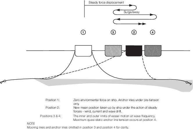
Figure 8.3.1 Quasi-static analysis
Table 8.3.1 Minimum anchor line factors of
safety
| Design Case
|
Description
|
Factor of safety
|
| Class notation
|
|
PM, PM(T1) etc.
|
PMC, PMC
(T1)
|
| 1
|
Operating – Intact
The
ship in an operating mode with its mooring system intact, subject to
specified operating constraints (limiting environment and permissible offset
of the ship).
|
2,7
|
3,0
|
| 2
|
Survival – Intact
The
ship in survival mode with mooring system intact, subject to maximum
(survival) environmental conditions.
|
1,8
|
2,0
|
| 3
|
Operating – Damaged
As
Case 1, but with loss of restraint of any one anchor line, see also
Note 3.
|
1,8
|
2,0
|
| 4
|
Survival – Damaged
As Case 2, but
with loss restraint of any one anchor line.
|
1,25
|
2,0/1,4
(See Note 5)
|
Note
1. In the context of this Chapter, Cases
1 and 2 (‘Intact’ Cases) refer to the mooring system with all anchor
lines intact. Cases 3 and 4 (‘Damaged’ Cases) refer to the mooring
system with the loss of any one anchor line.
|
Note
2. Anchor line factor of safety = 
|
Note
3. The factors of safety given in Table 8.3.1 Minimum anchor line factors of
safety are to be based on maximum
line tensions resulting from steady force offset of the ship, plus
maximum first order wave motion. In Design Cases 3 and 4, the factors
relate to the ship in its post-damage settled position, following the
loss of restraint from an anchor line, (i.e. neglecting transient
effects, but see Note 4).
|
Note
4. In addition to the ‘static’
considerations in Design Cases 3 and 4 (see Note 3), account is
also to be taken of transient vessel motions following anchor or line
failure. The motion path taken by the vessel in moving to a new static
equilibrium position is to be determined for each line breakage case
to ensure that:
(a) The ship maintains adequate
clearance from any adjacent installation (applicable where PMC
or PMC
(T1) etc. notation is to be assigned). A minimum dimensional
clearance of 10 m will normally be required.
(b) The
ship remains within its required operational excursion
limits.
(c) Successive line failures will not occur. In
calculating factors of safety, the maximum anchor line tensions in
this case are to be those resulting from the extreme point of
transient motion, with the ship subject to steady force and
significant wave motion.
|
Note
5. The factor of safety of 2,0 applies to
critical lines maintaining separation between the moored ship and an
adjacent installation.
|
Table 8.3.2 Thruster allowance
| Case
|
Thruster allowance
|
| (T1)
|
(T2)
|
(T3)
|
Operating
(Intact)
|
None
|
70% of all thrusters, less one
|
All thrusters, less one
|
Survival
(Intact)
|
70% of all thrusters
|
All thrusters
|
All thrusters
|
Operating
(Damaged)
|
None
|
70% of all
thrusters, less one
|
All
thrusters, less one
|
Survival
(Damaged)
|
70% of all thrusters
|
All thrusters
|
All thrusters
|
Note
2. Where all thrusters are permitted, the
net effect of all thrusters can be included in calculations.
Note
3. Where all thrusters except one are
permitted, the net effect of all thrusters, less the single most
effective one, can be included in calculations.
|
|
| Copyright 2026 Clasifications Register Group Limited, International Maritime Organization, International Labour Organization or Maritime
and Coastguard Agency. All rights reserved. Clasifications Register Group Limited, its affiliates and subsidiaries and their respective
officers, employees or agents are, individually and collectively, referred to in this clause as 'Clasifications Register'. Clasifications
Register assumes no responsibility and shall not be liable to any person for any loss, damage or expense caused by reliance
on the information or advice in this document or howsoever provided, unless that person has signed a contract with the relevant
Clasifications Register entity for the provision of this information or advice and in that case any responsibility or liability is
exclusively on the terms and conditions set out in that contract.
|
 |
|