
Section
2 Application of ice class to hull structures
2.1 General
2.1.1 The application
of bow requirements to the stern for Stern First Ice Class Ships in
this Section is intended to substitute the FS Rules and PC Rules requirements
for the stern of the ship. Application of other ice class rules to
the hull structure may be considered, taking into account the philosophy
of this Chapter.
2.1.2 For Stern First Ice Class Ships, the requirements of the bow region of the
FS Rules or the bow and bow intermediate areas of the PC Rules are to be applied to the
stern, taking into account the stern hull form dimensions, extents and requirements of
this Chapter.
2.1.3 The application
of ice class Rules to the stern and bow may be different if non-standard
scenarios are assumed. As a minimum, the stern is to comply with the
requirements of a stern for the assigned ice class. See
Ch 1, 3.1 Assignment of ice class 3.1.4.
2.1.4 The extent
of consideration for the stern hull structure of Stern First Ice Class
Ships is from amidships forward in the stern first mode.
2.2 Definitions
2.2.1
0°
WL angle (bow). The line that connects points where, in the
first instance from the bow, the angle between the waterline and the
centreline is zero, commonly termed forward flat of side.
For application of FS Rules, this corresponds to the border of the
part of the side where waterlines are parallel to the centreline nearest
to the bow.
2.2.2
10°
WL angle (bow). The line that connects points where, in the
first instance from the bow, the angle between the waterline and the
centreline is ten degrees.
2.2.3
0°
WL angle (stern). The line that connects points where, in the
first instance from the stern, the angle between the waterline and
the centreline is zero, commonly termed aft flat of side.
For application of FS Rules, this corresponds to the forward border
of the part of the side where waterlines are parallel to the centreline
nearest to the stern.
2.3 Definition of hull angles for the stern
2.3.1 For application
of requirements for PC Rules, the waterline angle, α, at the stern,
is to be interpreted using Figure 3.2.2 Interpretation of waterline angles for Stern First Ice Class Ships. The waterline length is to be divided into four sub-regions
of equal length. The force F, line load Q,
pressure P, and load aspect ratio, AR, are
to be calculated with respect to the mid-length position of each sub-region. See
Pt 8, Ch 2 Ice Operations - Ice Class of the Rules
for Ships.
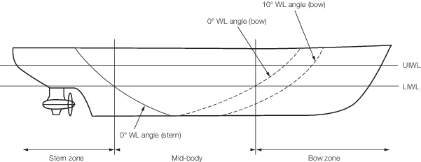
Figure 3.2.1 Definition of waterline angles

Figure 3.2.2 Interpretation of waterline angles for Stern First Ice Class Ships
2.3.2 For a single
propulsion unit installation, the waterline angles are to be interpreted
as if the stern centreline were a bow stem. For twin propulsion unit
installations, the waterline angles inboard of the centreline of the
propulsion unit need not be considered.
2.4 Stern hull areas
2.4.2 If the ship is designed with two sets of UIWL and LIWL for operating forward
and stern first in ice, whichever gives the greater requirement is to be considered for
hull area definition purposes.
2.4.3 For FS Rule application, the shoulder region is to be divided into two
areas. The shoulder ice belt reigon is the area enclosed by the upper extent of the ice
belt, X, and lower extent of the ice belt, Y, and bound longitudinally
from K to Z. The lower shoulder region Sl is the region bound by
the lower extent of the ice belt and a line from the point of intersection of K
with the baseline to the point of intersection between W and a vertical line
where the 0° WL line intercepts with the LIWL. See
Figure 3.2.3 Ice-strengthening extents for
stern.
2.4.4 For FS Rule application, the forward and shoulder ice belt regions define the required
extent of strengthening for plating. The upper vertical extension of ice strengthening
of framing for these ice belt regions is to be taken as 1,0 m above the UIWL. The lower
vertical extension of ice strengthening of frames for these ice belt regions is to be
taken as 1,6 m below the LIWL. The lower vertical extension of framing for the lower
shoulder region need not be greater than the lower extent of the plating.
2.4.5
K is the forward extent (considering the ship in the stern first mode) of the bow
region for PC Rule application and the extent of forward strengthening required below
the ice belt for FS Rule application. For FS Rule application, K, is defined as
five frame spaces forward of the intersection with the foot of the skeg. For PC Rule
application or where no skeg is fitted, K may be taken as 0,7b aft
(considering the ship in the stern first mode) from the centreline of the propulsion
unit slewing column, where b is the half breadth at UIWL at the centreline of the
propulsion unit slewing column.
2.4.6 For FS Rule application, the shoulder ice belt is to be considered a
continuation of the forward region. The lower shoulder region, Sl, is to have
scantlings determined according to midship region requirements.
2.4.7 The aft extent, of the bow intermediate area for PC Rule application or
shoulder region for FS Rule application Z, is to be located 0,04 L aft of
the point of intersection between the 0° WL line and the LIWL (with the ship in the
stern first mode) or at the point of intersection between the 0° WL line and the lower
extent of the ice belt region, whichever gives the greater extent of strengthening.
2.5 Application to Icebreakers
2.5.1 The requirements
of Figure 3.2.3 Ice-strengthening extents for
stern, based on the
hull standard load scenarios, may be applied to ships assigned the
notation Icebreaker. However, additional scenarios may
need to be considered due to the specialist operational nature of
such ships and the particulars of the hull form.
2.5.2 For icebreakers,
it is considered that the consistent application of the philosophy
of Ch 3, 2.4 Stern hull areas, should be followed alongside
the icebreaker’s particular operational and load scenarios.
2.5.3 For icebreakers
where the intercept of the 0° WL angle (stern) line with the UIWL
and LIWL is near coincident, the value of Z is to be
specially considered but is to be taken as 0,08L or 6
m, whichever gives the greater value.
2.5.4 For icebreakers
where no parallel mid-body 0° WL angle (stern) exists, the extent
of stern strengthening is to be specially considered. In general,
the bow intermediate area is to extend aft from K by
0,2L.
2.6 Additional requirements
2.6.1 For PC
Rule application, the bow region is to extend to the bottom shell
in way of the propulsion unit(s). For FS Rule application, the forward
region is to extend to the bottom shell in way of the propulsion unit(s).
2.6.2 For Stern
First Ice Class Ships where different ice classes are used as a strengthening
basis for stern first and bow first operating modes, the requirements
for the midship region shall be taken from the higher ice class.
2.7 Strength level
2.7.1 For the
application of PC Rule requirements, the area factors to be applied
to the bow and bow intermediate areas for PC application are given
in Table 3.2.1 PC Rule Area Factors for bow and
bow intermediate regions applied to the stern of SFIC ships.
Table 3.2.1 PC Rule Area Factors for bow and
bow intermediate regions applied to the stern of SFIC ships
| Ice Class assigned
|
Bow
|
Bow Intermediate Ice belt
|
Bow Intermediate lower
|
Bow Intermediate bottom
|
| PC1
|
0,85
|
0,85
|
0,65
|
0,50
|
| PC2
|
0,85
|
0,85
|
0,65
|
0,45
|
| PC3
|
0,85
|
0,80
|
0,60
|
0,40
|
| PC4
|
0,85
|
0,80
|
0,55
|
0,35
|
| PC5
|
0,85
|
0,80
|
0,55
|
0,30
|
| PC6
|
0,85
|
1,00
|
0,50
|
0,25
|
| PC7
|
0,85
|
1,00
|
0,50
|
0,25
|
2.8 Stern stem
2.8.1 Suitable
strengthening is required at the stern, where the stern intersects
the upper and lower ice waterlines.
2.8.2 The reinforcement
of the stern stem is to be plated and well connected to the internal
structure.
2.8.3 For single
propulsion unit installations, the stern stem is located at the centreline
and should be suitably connected to the centreline girder.

Figure 3.2.4 Example of stern stem arrangement
|