
Section
2 Materials
2.1 Manufactured at approved works
2.1.1 The Rules for
Naval Ships state that ‘Materials are to be made at works which
have been approved by the Committee for the type of product being
supplied’. It is the building port Surveyor’s responsibility
to ensure that a Builder is aware of this requirement and verify that
it is complied with. Approved Works are detailed in the Lists of Approved
Manufacturers of Materials and Recognized Proving Establishments.
2.2 Verification of steel plate and sections
2.2.1 The need to
ensure that all structural material for classed ships is certified
by the Surveyors in accordance with LR’s requirements should
be impressed on Builders at the design stage, and it should be checked
that test certificates or shipping statements in accordance with LR’s
Rules are furnished by the steel manufacturers when the material is
delivered. It is appreciated that Surveyors in the building yards
cannot see and check every piece of material from its arrival at the
stockyard through to erection, but they must satisfy themselves by
random checks that the yard system is adequate in this respect. When
material is shot-blasted and primed on reception, the steelwork’s
identification marks should be clearly marked with the appropriate
colour code. This checking of material with the test certificates
should be done at the earliest possible stage in order to prevent
the use of material which has not been properly tested and verified
at the steelworks. These certificates also afford an early opportunity
to verify that material is being supplied to the approved scantlings.
2.3 Defects in steel products
2.3.1 Surface inspection
is the responsibility of the steelmaker and the Surveyor at the steelworks
does not normally undertake this work unless it is particularly specified.
Where defects are found after delivery to the Builder, any rectification
should be agreed and should generally be in accordance with the Rules
for Materials.
2.3.2 The limits
of depth and extent of rounded surface defects on plate, cast or forged
material in relation to the material plate thickness are shown in Table 3.2.1 .
Thickness
of
material (mm)
|
Maximum permissible
depth of defect (mm)
|
|
|
Area
affected
greater than 5%
|
Area
affected
less than 10%
|
| <8
|
0,2
|
0,4
|
| 8 to 25
|
0,3
|
0,5
|
| 25 to 40
|
0,4
|
0,6
|
| 40 plus
|
0,5
|
0,7
|
Note
1. Defects are to be measured after shot
blasting or plate cleaning.
Note
2. The depth of the deepest imperfection
is to be considered.
Note
3. Defects not exceeding the limits shown
need not be repaired.
Note
4. Fracture defects are always to be
repaired irrespective of their depth.
|
2.3.3 Defects are
to be made good by grinding only, subject to the plate thickness not
being reduced by more than seven per cent of the nominal thickness
or 3 mm, whichever is the lower, and the area involved not exceeding
two per cent of the surface area.
2.3.4 When the limits
in Table 3.2.1 are exceeded, plates
are to be made good by grinding followed by welding.
2.3.5 Where the depth
of the deepest imperfection exceeds 20 per cent of the nominal thickness,
or the defective area exceeds two per cent of the total surface area,
such areas are to be cropped and replaced, or the material rejected.
2.3.6 Complete removal
of the defects is to be verified by suitable non-destructive examination
techniques and after welding repair is to be proved free from further
defects.
2.3.7 Care is to
be taken in the repair of defects in higher tensile steel. Low hydrogen
electrodes with similar properties to the higher tensile steel are
to be used with preheating as necessary.
2.3.8 Plates in which
laminations are suspected or detected are to be ultrasonically tested
to determine the full extent of such laminations. Areas of lamination
are to be removed.
2.3.9 Defective plate,
with defects in excess of those stated, is to be cropped back and
replaced or material rejected.
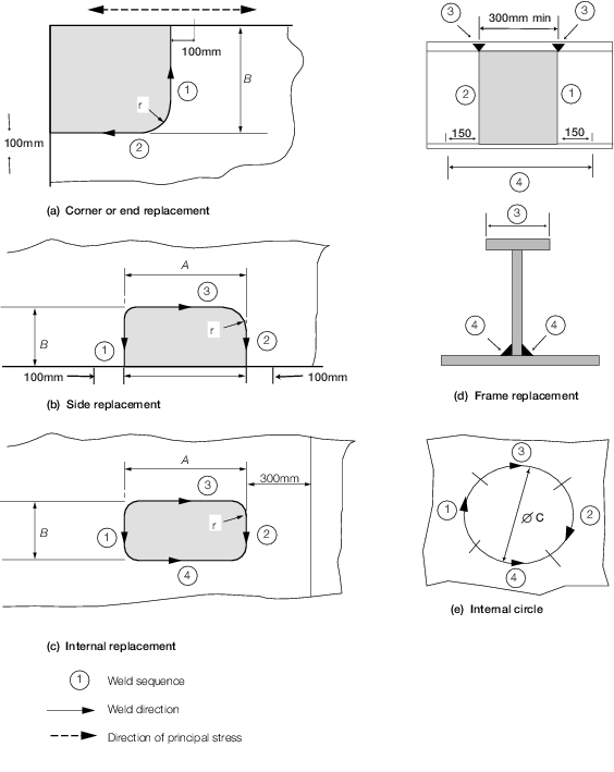
2.4 Part replacement of plates
2.4.1 When defects
exceed the limits shown below, the portion of the plate affected is
to be cropped and replaced. Plate inserts are to be arranged in accordance
with Table 3.2.1 Part replacement of plates and the alignment
of inserts is to be in accordance with Table 3.2.1 Part replacement of plates.
Table 3.2.1 Part replacement of plates
| A x B
|
Parts to be replaced
|
Strength members
|
Elsewhere
|
| End and corner of plate
|
300 x 1000
|
300 x 300
|
| Side of plate
|
300 x 300
|
300 x 300
|
| Insert
|
300 x 300
|
300 x 300
|
| C
|
Circular insert
|
dia. 300
|
dia. 150
|
Line of plate replacement to be not less than 100 from extreme
edge of defect.
All dimensions are in mm.
Weld
sequence given by figure (1)
|
|
Note
1. All dimensions are minimum.
Note
2. Rolling direction of replaced plate to
be the same as that of the parent plate.
Note
3. Minimum distance from outermost defect
to line of weld – 100 mm.
|
Note
4. Dimensions in millimetres:
r = 12%B, 5t or 75 mm whichever is the greater.
Note
5. Stiffener web butt weld scallop to be
filled on final pass (4).
Note
6. Insert welds are not to be within 75
mm of butts, seams, internal structure or other inserts.
|
2.5 Structural forgings, castings and prefabrications
2.5.1 All large or
important forgings, castings and prefabrications, such as sternframes,
rudders, rudderstocks, rudder axles, quadrants or tillers, require
to be examined and tested in accordance with the Rules for Materials
by the Surveyor attending the manufacturer’s works. Procedures
for the identification and certification of all such items (excluding
prefabrications) are detailed in the Rules for Materials and the Surveyors
at the building yard should ensure that they receive appropriate certificates
for the items intended for the vessel building under their survey.
The markings on the items should be checked against the certificates.
2.5.2 When, at the
manufacturer’s request, limitations have been agreed upon the
extent of Non-Destructive Examination (NDE) carried out on an item
in a semi-finished, rough machined, or part machined condition, the
Surveyor at the manufacturers will have made a statement to this effect
on the certificate for the item. When work is subsequently carried
out upon such an item at the shipyard, the Surveyor at the building
port should consider further NDE. Where further NDE is carried out
on the item, this should be indicated on its final certificate.
2.6 Raw material surface tolerances
2.6.1 The surface
cleanliness of the materials in preparation for painting is to be
in accordance with national or paint manufacturer’s standards.
2.6.2 Where approved
corrosion control coatings are to be used, the quality of surface
treatment is to be in accordance with the grade specified in the approval
documents.
2.7 Welding consumables
2.7.1 All welding
consumables are to be approved in accordance with the requirements
of the Rules for Materials, and selected from the List of Approved
Welding Consumables for use in Ship Construction.
2.7.2 Surveyors should
satisfy themselves that all storage spaces provided by the Builder
will maintain welding consumables in good condition. They should also
ensure satisfactory arrangements for their maintenance after issue
to the work force, and for compliance with manufacturer’s instructions
regarding use of their product. Systematic checks should be made on
the consumables being used, having regard to the grades of steel and
welding positions involved.
2.8 Non-destructive examination
2.8.2 Acceptance
criteria are given in Table 3.2.2 Weld defect acceptance levels for
fabrication.
Table 3.2.2 Weld defect acceptance levels for
fabrication
| Defect type
|
Permitted
maximum
|
| Undercut
|
Slight intermittent undercut is
permitted, provided the depth does not exceed 0,5 mm
|
| Shrinkage grooves/root
concavities
|
Slight intermittent shrinkage grooves,
and root concavities permitted to a maximum depth of 1,2 mm
|
| Excess penetration
|
3 mm max
|
| Misalignment
|
t/5 but 3 mm max
|
| Crack (including lamellar
tears)
|
Not permitted
|
|
Lack of root fusion
Lack of side-wall fusion
Lack of inter-run fusion
Lack of root penetration
|
Not permitted
Not permitted
Not permitted
Slight lack of penetration permitted (L = t but
25 mm max)
Aggregate length not to exceed t in a length of
12t
|
| POROSITY
|
|
| Individual pore
|
3mm for t up to 50 mm
4,5 for t over 50 mm and up to 75mm
6,0 mm for t over 75 mm
|
| Uniformly distributed
porosity
|
2% by area of the weld
|
| SLAG
|
|
| Individual and parallel to weld
axis
|
L = t but 25 mm max
W = 1,5 mm max
|
| Linear group
|
Aggregate length not to exceed
t in a length of 12t
|
| Symbols
|
|
t
|
= |
plate thickness of thinnest plate in welded
connection |
|
|
| Copyright 2022 Clasifications Register Group Limited, International Maritime Organization, International Labour Organization or Maritime
and Coastguard Agency. All rights reserved. Clasifications Register Group Limited, its affiliates and subsidiaries and their respective
officers, employees or agents are, individually and collectively, referred to in this clause as 'Clasifications Register'. Clasifications
Register assumes no responsibility and shall not be liable to any person for any loss, damage or expense caused by reliance
on the information or advice in this document or howsoever provided, unless that person has signed a contract with the relevant
Clasifications Register entity for the provision of this information or advice and in that case any responsibility or liability is
exclusively on the terms and conditions set out in that contract.
|
 |
|