
Section
1 General
1.1 Application
1.1.1 The
requirements for longitudinal and transverse global strength are contained
within this Chapter.
1.1.2 This
Chapter contains Sections detailing the analysis requirements for
the following topics:
- Hull girder strength.
- Extreme strength assessment.
- Residual strength assessment
1.1.3
Section
2, Hull girder strength. This Section specifies the hull girder
strength requirements based on the conventional elastic design and
buckling analyses. All ships are to comply fully with the requirements
of this Section.
1.1.4
Section
3, Extreme strength assessment. This Section specifies the
requirements for the assessment of the extreme hull girder strength
to withstand wave loads that have a low probability of occurring during
the life of the ship. This is an optional assessment and ships which
comply with the extreme strength requirements can apply for the notation ESA1 or ESA2, see
Vol 1, Pt 1, Ch 2, 3.7 Hull strength notations 3.7.1
1.1.5
Section
4, Residual strength assessment. This Section specifies the
requirements for the assessment of the residual hull girder strength
after the ship has sustained structural damage. This is an optional
assessment and ships which comply with the residual strength requirements
can apply for the notation RSA1, RSA2 or RSA3, see
Vol 1, Pt 1, Ch 2, 3.7 Hull strength notations 3.7.1.
1.2 Hull girder strength notations
1.2.1 The
following notations are available for all ships with regard to global
hull girder strength aspects:
-
ESA1, ESA2 Extreme strength assessment.
-
RSA1, RSA2, RSA3 Residual strength assessment.
A distinction is made between levels of performance and levels
of assessment; the numeral in the notation reflects the level of assessment.
Levels of performance are denoted by the letters A, B, C for collision
or grounding damage and numerals I, II and III for damage from military
threats and are confidential to the Owner. See
Vol 1, Pt 6, Ch 4, 4.2 Extent of damage and analysis for non-military threats and Vol 1, Pt 4, Ch 2, 7 Residual strength for military threats.
1.2.2 The
performance of the ship with respect to extreme hull girder strength
aspects may be evaluated at two levels. ESA1, the lowest
level offers a basic assessment of the ship’s capability. ESA2, the higher level is a much more rigorous assessment of the
hull’s capability to withstand extreme sea states.
1.2.3 It is
recommended that ships of groups NS1 and NS2 should comply with ESA1. However, it is the responsibility of the Owner to specify
the level of extreme strength assessment required.
1.2.4 The
extreme strength assessment level adopted must reflect the performance
level required by other notations.
1.2.5 The
two levels of assessment available for the extreme strength assessment
notation are summarised as follows:
|
ESA1
|
= |
This uses elastic
theory, based on the section moduli and area, and determination of
the buckling strength to resist the global hull girder loads. The
assessment is to be made at a minimum of three locations. |
|
ESA2
|
= |
Uses a ‘2D’
ultimate strength beam representation and a failure level criterion
based on the section ultimate bending moments being satisfactory compared
to the design bending moments in both hogging and sagging. This will
require assessment using ultimate strength calculations at all critical
longitudinal locations. |
1.2.6 The
performance of the ship with respect to residual strength aspects
may be evaluated at several levels. The lowest level offers a basic
assessment of the ship’s capability to survive. Higher residual
strength levels are designed to show that the ship has an improved
performance with respect to hull’s capability to withstand increased
damage extents and scenarios.
1.2.7 Three
assessment and performance levels are available for the residual strength
assessment notation. RSA1, the assessment Level 1 residual
strength assessment, and performance level A are recommended as a
minimum for all ships of groups NS1 and NS2.
However, it is the responsibility of the Owner to specify the level
of residual strength assessment required.
1.2.8 The
residual strength assessment level adopted must reflect the performance
level required by other notations.
1.2.9 The three levels of assessment available for the residual strength
assessment notation are summarised as follows:
|
RSA1
|
= |
This uses elastic
theory, based on the remaining section moduli and area after damage,
and determination of the buckling strength to resist the global hull
girder loads. The assessment is to be made at a minimum of three critical
sections. |
|
RSA2
|
= |
Uses a ‘2D’
ultimate strength beam representation and a failure level criterion
based on the section ultimate bending moments being satisfactorily
compared to the design bending moments in both hogging and sagging.
The assessment is to be made at a minimum of three critical sections. |
|
RSA3
|
= |
Uses a ‘3D’
definition of a section of the hull girder and relies on geometric
and material failure criteria implicit in the chosen finite element
code. It could also include coupled Euler-Lagrange formulations to
specifically account for internal and external blast effects, UNDEX
shock and whipping. |
1.3 Symbols and definitions
1.3.1 The
symbols and definitions applicable to this Chapter are defined below
or in the appropriate sub-Section.
|
L
R
|
= |
Rule length of the ship, in metres |
|
σ
ο
|
= |
specified minimum yield strength of the material, in N/mm2
|
|
τ
ο
|
= |

|
1.3.2 The
strength deck is to be taken as follows:
-
Where there is
a complete upper deck, the strength deck is the upper deck.
-
Where the upper deck is stepped, as in the case of ships with a
raised quarterdeck, the strength deck is also stepped, see
Vol 1, Pt 6, Ch 4, 1.4 Calculation of hull section modulus. Adequate provision should be made for the transfer of load between
the stepped decks.
1.4 Calculation of hull section modulus
1.4.1 In general, the effective sectional area of continuous longitudinal
strength members, after deduction of openings, is to be used for the calculation of
midship section modulus.
1.4.2 Structural members which contribute to the overall hull girder strength are
to be carefully aligned so as to avoid discontinuities resulting in abrupt variations of
stresses and are to be kept clear of any form of openings which may affect their
structural performances.
1.4.3 In general, short superstructures or deckhouses will not be accepted as
contributing to the global longitudinal or transverse strength of the ship. However,
where it is proposed to include substantial, continuous stiffening members, special
consideration will be given to their inclusion on submission of the designer’s/builder’s
calculations, see also
Vol 1, Pt 6, Ch 4, 2.5 Superstructures global strength
1.4.4 A transition zone, see
Figure 4.1.1 Strength deck stepping, is
to be assumed at the ends of stepped decks where the longitudinal structural material
cannot be included in the calculation of the section modulus of hull sections. The
length of the zone is to be taken as four times the deck height. Local insert plates are
to be fitted in the side shell as appropriate with a thickness at least 25 per cent
greater than the adjacent plating. They are to extend a minimum of one primary frame
spacing forward and aft, but are to be not less than 1500 mm each way from the end of
the transition zone. For vessels with complex arrangements or geometries, shadow area
plans are to be submitted.
1.4.5 A superstructure deck can only be considered as a strength deck and
included in the calculation of the section modulus of hull sections if it extends over
the full 0,4LR midship region and out to the side shell with the
transition zones being located outside the 0,4LR midship region,
see
Figure 4.1.2 Strength deck stepping, superstructure deck.
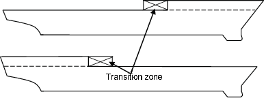
Figure 4.1.1 Strength deck stepping
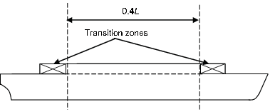
Figure 4.1.2 Strength deck stepping, superstructure deck
1.4.6 Where continuous deck longitudinals or deck girders are arranged above the
strength deck, special consideration may be given to the inclusion of their sectional
area in the calculation of the hull section modulus, Z. The lever is to be taken
to a position corresponding to the height of the longitudinal member above the moulded
deck line at side amidships. Each such case will be individually considered.
1.4.7 Adequate transition arrangements are to be fitted at the ends of effective
continuous longitudinal strength members in the deck and bottom structures.
1.4.8 Scantlings of all continuous longitudinal members of the hull girder based
on the minimum section stiffness requirements determined from 2.2 are to be maintained
within 0,4L
R amidships. However, in special cases, based on consideration of type of
ship, hull form and loading conditions, the scantlings may be gradually reduced towards
the ends of the 0,4L
R part, bearing in mind the desire not to inhibit the ship’s loading and
operational flexibility.
1.4.9 Structural material which is longitudinally continuous but which is not
considered to be fully effective for longitudinal strength purposes will need to be
specially considered. The global longitudinal strength assessment must take into account
the presence of such material when it can be considered effective. The consequences of
failure of such structural material and subsequent redistribution of stresses into or
additional loads imposed on the remaining structure must be considered.
1.4.10 In particular, all longitudinally continuous material will be fully
effective in tension whereas this may be not be so in compression due to a low buckling
capability. In this case, it may be necessary to derive and apply different hull girder
section moduli to the hogging and sagging bending moment cases.
1.4.11 Openings in decks, longitudinal bulkheads and other longitudinal effective
material having a length in the fore and aft directions exceeding 0,1B m or 2,5 m
or a breadth exceeding 1,2 m or 0,04B m, whichever is the lesser, are in all
cases to be deducted from the sectional areas used in the section modulus calculation.
1.4.12 Openings smaller than stated in Vol 1, Pt 6, Ch 4, 1.4 Calculation of hull section modulus 1.4.11, including manholes, need not be deducted provided
they are isolated and the sum of their breadths or shadow area breadths, see
Vol 1, Pt 6, Ch 4, 1.4 Calculation of hull section modulus 1.4.15, in one transverse section does reduce the section
modulus at deck or bottom by more than 3 per cent.
1.4.13 The expression 0,06 (B
1 – Σb
1 ), where B
1 equals the breadth of the ship at the section considered and Σb
1 equals the sum of breadths of deductible openings, may be used for deck
openings in lieu of the 3 per cent limitation of reduction of section modulus in Vol 1, Pt 6, Ch 4, 1.4 Calculation of hull section modulus 1.4.12.
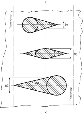
Figure 4.1.3 Isolated openings
1.4.14 Where a large number of openings are proposed in any transverse space,
special consideration will be required.
1.4.15 Where calculating deduction-free openings, the openings are assumed to have
longitudinal extensions as shown by the shaded areas in Figure 4.1.3 Isolated openings The shadow area is obtained by drawing two
tangent lines to an opening angle of 30°. The section to be considered is to be
perpendicular to the centreline of the ship and is to result in the maximum deduction in
each transverse space.
1.4.16 Isolated openings in longitudinals or longitudinal girders need not be
deducted if their depth does not exceed 25 per cent of the web depth or 75 mm, whichever
is the lesser.
1.4.17 Openings are considered isolated if they are spaced more than 1 m
apart.
1.4.18 A reduction for drainage holes and scallops in beams and girders, etc. is
not necessary so long as the global section modulus at deck or keel is reduced by no
more than 0,5 per cent.
1.5 General
1.5.1 The
Level 1 assessment procedures specified in Clasifications Register’s
(hereinafter referred to as 'LR') Structural Detail Design Guide for
fatigue design assessment, FDA, are to be generally applied
to the construction details of all ships.
1.6 Direct calculations
1.6.1 Direct
calculations using finite element analysis may be necessary for ships
with complicated longitudinal structural arrangements such as ships:
- of novel design;
- with significant discontinuous longitudinal material;
- with large deck openings, or where warping stresses in excess
of 14,7 N/mm2 are likely to occur;
- with large openings in the side shell, especially in way of the
sheerstrake.
|