
Section
2 Structural resistance
2.1 Assessment of stresses in structural components
2.1.1 The
equations and methods given below are to be used to derive the stresses
acting within plating and within stiffeners and beams.
2.1.2 These
equations are valid for plating and beams subjected to lateral, or
normal, pressure or point loads, i.e. local design considerations.
2.2 Stresses in plating
2.2.2 The bending stress in a plate panel between stiffeners due to a uniform
lateral pressure is to be calculated as follows:
where
|
p
|
= |
lateral pressure, in kN/m2
|
|
t
p
|
= |
thickness of plating, in mm |
|
s
|
= |
spacing of secondary stiffeners, in mm |

|
= |
length of the plate panel, in metres |
Note: The plate bending stresses are to be based on the actual stiffener
spacing.
2.2.3 The
direct stress in a plate panel subjected to membrane or in-plane loading
is to be calculated as follows:
where
|
L
|
= |
in-plane
load on the panel of plating, in kN |
|
A
|
= |
area
normal to the load, L, in cm2, ignoring secondary stiffeners
which are not continuous but may include deep beams.
|
2.2.4 The
shear stress in a plate panel is to be calculated as follows:
where
|
Q
|
= |
shear
force acting on the panel of plating |
|
A
|
= |
cross-sectional
area of the panel in the direction of the shear force, in cm2
|
| = |
t
p
b
v or t
p
b
t
|
b
t and b
v are
the total breadth of the plate panel over which the shear force acts.
2.3 Stresses in secondary and primary member stiffeners
2.3.1 The
bending stresses, deflection and shear stress in stiffeners or beams
due to lateral pressure loading or point loads are to be derived as
given below.
2.3.2 The
stresses in the stiffener flange, σ
sf,
and the attached plating to the stiffener, σ
sp,
due to the applied load are illustrated in Figure 3.2.2 Bending stresses in stiffener beam and may be derived using
the formulae given below.
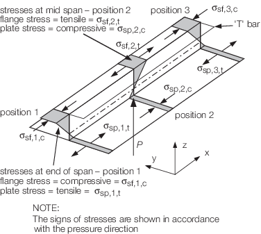
Figure 3.2.2 Bending stresses in stiffener beam
2.3.3
Bending
stresses
Bending stress due to a lateral pressure
load
Bending stress due to a point load or force
Bending stress due to an applied end deflection
2.3.4
Beam
deflection
Deflection in beam due to a lateral pressure load
Deflection in beam due to point load
2.3.5
Shear
stresses
Shear stress in beam due to a lateral pressure load
Shear stress in beam due to a point load
Shear stress in beam due to an applied end deflection
where
|
p
|
= |
lateral
pressure, in kN/m2
|
|
δ |
= |
applied deflection,
in mm |
s
p is the stiffener spacing,
in mm
s
p is to be taken as s for
secondary stiffeners and 1000S for primary members, see
Vol 1, Pt 6, Ch 2, 1.3 Symbols and definitions 1.3.1
Z
f and Z
p are
the section moduli, in cm3, of the stiffener including
attached plating at the flange and attached plating respectively

|
= |
section modulus, in cm4
|
|
A
w
|
= |
web area of stiffener, in cm2
|
|
E
|
= |
modulus
of elasticity, in N/mm2.
|
|
| Copyright 2022 Clasifications Register Group Limited, International Maritime Organization, International Labour Organization or Maritime
and Coastguard Agency. All rights reserved. Clasifications Register Group Limited, its affiliates and subsidiaries and their respective
officers, employees or agents are, individually and collectively, referred to in this clause as 'Clasifications Register'. Clasifications
Register assumes no responsibility and shall not be liable to any person for any loss, damage or expense caused by reliance
on the information or advice in this document or howsoever provided, unless that person has signed a contract with the relevant
Clasifications Register entity for the provision of this information or advice and in that case any responsibility or liability is
exclusively on the terms and conditions set out in that contract.
|
 |
|