
Section
4 Design and construction
4.1 General
4.1.1 The arrangement of all types of thrusters is to be such that the vessel can
be manoeuvred in accordance with the design specifications. The operating conditions
covered are to include the following:
- Maximum continuous shaft power/speed to the propeller in the ahead
condition at the declared steering angles and conditions.
- Manoeuvring speeds of the propeller shaft and/or reversing mechanism
in the ahead and astern direction at the declared steering angles and sea
conditions.
- The stopping manoeuvre described in Vol 2, Pt 1, Ch 3, 17.3 Performance testing requirements for naval vessels 17.3.9.
- Astern running conditions for the ship.
4.1.3 In addition
to the requirements of this Section, reference is to be made to:
-
Main transmission
gearing, Vol 2, Pt 3, Ch 1 Gearing.
-
Main transmission
shafting, Vol 2, Pt 3, Ch 2 Shafting Systems.
-
Propelle,r Vol 2, Pt 4, Ch 1 Propellers.
-
Torsional vibration, Vol 2, Pt 5, Ch 1 Torsional Vibration.
-
Lateral vibration
for shafting systems which include cardan shafts, Vol 2, Pt 5, Ch 3 Lateral Vibration.
-
Steering arrangements, Vol 2, Pt 6, Ch 1 Steering Gear.
4.2 Azimuth thrusters
4.2.2 Where more than one azimuth thruster is fitted, Vol 2, Pt 6, Ch 1, 4.1 General 4.1.2 is considered to be
met when:
- Each azimuth thruster
fulfils the requirements for main steering gear (see
Vol 2, Pt 4, Ch 3, 4.2 Azimuth thrusters 4.2.3); and
- Each azimuth thruster is
provided with the ability to position and lock the azimuth thruster in a neutral
position after a failure of its own power unit(s) and actuator(s). These
arrangements are to be of sufficient strength to hold the azimuth thruster in
position at the ship's manoeuvring speed to be taken as not less than 7 knots.
Instructions displayed at the locking mechanism’s operating position are to
include a directive to inform the bridge of any limitation in ship's speed
required as a result of the securing mechanism being activated.
4.2.3 The main steering gear is to be:
- Of adequate strength and
capable of changing direction of the ship’s azimuth thruster from one side to the
other in accordance with the declared steering angle limits at an average turning
speed of not less than 2,3 deg/s with the ship running ahead at maximum ahead
service speed which shall be demonstrated in accordance with Vol 2, Pt 1, Ch 3, 14.2 Azimuth thrusters and Vol 2, Pt 1, Ch 3, 17.3 Performance testing requirements for naval vessels;
- Operated by power; and
- So designed that they will
not be damaged at maximum astern speed ; this design requirement need not be
proved by trials at maximum astern speed and declared steering angle limits.
4.2.4 The auxiliary steering gear is to be:
- Capable of being brought
speedily into action in an emergency; and
-
Of adequate strength and capable of changing the direction of the
ship’s azimuth thrusters from one side to the other in accordance with the
declared steering angle limits at an average turning speed of not less than 0,5
deg/s with the ship running ahead at one half of the maximum ahead service speed
or 7 knots, whichever is the greater; and
-
Operated by power for ships having propulsion power of more than 2500
kW per thruster unit and for all ships, where it is necessary to meet the
requirements of Vol 2, Pt 4, Ch 3, 4.2 Azimuth thrusters 4.2.4.(b).
4.2.5 In addition to the requirements in Vol 2, Pt 4, Ch 3, 1.2 Redundancy 1.2.1, for ships fitted
with a single azimuth thruster, where the main steering gear comprises two or more
identical power units and two or more identical steering actuators, auxiliary steering
gear need not be fitted provided that the steering gear:
- Is capable of satisfying the requirements in Vol 2, Pt 4, Ch 3, 4.2 Azimuth thrusters 4.2.3.(a) while any one of
the power units is out of operation; and
- Is arranged so that after a single failure in its piping system or in one of the
power units, steering capability can be maintained or speedily regained.
4.2.6 For ships fitted with more than one azimuth thruster, where each main steering system
comprises two or more identical steering actuating systems, auxiliary steering gear need
not be fitted provided that each steering gear:
- Is capable of satisfying the requirements in Vol 2, Pt 4, Ch 3, 4.2 Azimuth thrusters 4.2.3.(a)
while any one of the power units is out of operation; and
- Is arranged so that after a single failure in its piping or in one of the steering
actuating systems, steering capability can be maintained or speedily regained (e.g.
by the possibility of positioning the failed steering system in a neutral position in
an emergency, if needed). Consideration will be given to alternative arrangements
providing equivalence can be demonstrated.
The above capacity requirements apply regardless of whether the steering systems are
arranged with shared or dedicated power units.
4.2.7 The steering gear for azimuthing thrusters used for dynamic positioning
applications with an associated class notation, is to be capable of a maximum rotational
speed of not less than 9 deg/s.
4.2.8 Gearing for the azimuthing mechanism is to be designed to a recognised
National Standard and the following conditions:
- design maximum dynamic duty steering torque;
- a static duty (≤103 load cycles) steering torque which
should be not less than MT, as defined in Vol 2, Pt 4, Ch 3, 4.3 Azimuth thrusters with a nozzle 4.3.1;
- variable loading, where applicable. A spectrum
(duty) factor may be used. The load spectrum value is to be derived using load
measurements of similar units, where possible.
4.2.9 The following minimum factor of safety values are to be achieved:
- Surface Stress S
Hmin = 1,0.
- Bending Stress S
Fmin = 1,5.
4.3 Azimuth thrusters with a nozzle
4.3.1 Where the propeller is contained within a nozzle, the equivalent rudder
stock diameter in way of tiller, used in Table 3.2.4 Rudder stock diameter in Vol 1, Pt 3, Ch 3 Ship Control Systems, is to be determined as follows:

where
|
V
|
= |
maximum service speed, in knots, which the craft is designed to
maintain under thruster operation |
|
A
N
|
= |
projected nozzle area, in m2, and is equal to the length
of the nozzle multiplied by the mean external vertical height of the nozzle |
The corresponding maximum turning moment, M
T, is to be determined as follows:
4.3.2 In addition
to the requirements of Vol 1, Pt 3 Design Principles and Constructional Arrangements the
scantlings of the nozzle stock or steering tube are to be such that
the section modulus Z against transverse bending at any
section x–x is not less than:
where
|
T
M
|
= |
maximum thrust of the thruster unit, in tonnes. |
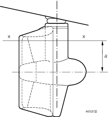
Figure 3.4.1 Azimuth thruster
4.3.3 The
scantlings of nozzle connections or struts will be specially considered.
In the case of certain high powered ships, direct calculation may
be required.
4.3.4 Where
the propeller is not contained in a nozzle, the scantlings in way
of the tiller will be subject to special consideration.
|