
Section
2 General requirements
2.1 Pod arrangement
2.1.1 In general, for a ship to be assigned an unrestricted service notation, a
minimum of two podded propulsion units is to be provided where these form the sole means
of propulsion. For vessels where a single podded propulsion unit is the sole means of
propulsion, an evaluation of a detailed engineering justification will be conducted by
LR, see
Vol 2, Pt 4, Ch 4, 2.2 Documentation required for design review 2.2.2. This evaluation process will include the appraisal
of a Risk Assessment (RA) to verify that sufficient levels of redundancy and monitoring
are incorporated in the podded propulsion unit’s support systems and operating
equipment.
2.2 Documentation required for design review
2.2.1 In addition
to the plans required by Vol 2, Pt 3, Ch 1 Gearing and Vol 2, Pt 3, Ch 2 Shafting Systems, Vol 2, Pt 4, Ch 1 Propellers, Vol 2, Pt 5 Shaft Vibration and Alignment, Vol 2, Pt 6, Ch 1 Steering Gear, Vol 2, Pt 7, Ch 3 Machinery Piping Systemsand Vol 2, Pt 9 Electrotechnical Systems and Vol 2, Pt 10 Human Factors, the following plans and information are
required to be submitted for appraisal. Where appropriate, the information
shall be contained in a System Design Description document, see
Vol 2, Pt 1, Ch 3, 3.5 System design description:
-
Description of
the ship’s purpose/capabilities together with the pod’s
intended operational modes in support of these capabilities. The operational
modes are to include stopping the vessel and restrictions on steering
angles at different ship speeds. See also
Vol 2, Pt 4, Ch 4, 2.2 Documentation required for design review 2.2.1.(h).
- The declared steering angle limits are to be stated by the steering system
manufacturer for each podded propulsion unit;
-
Power transmitted
at MCR condition (shaft power and rpm) and other maximum torque conditions,
e.g. bollard pull.
-
Maximum transient
thrust, torque and other forces and moments experienced during all
envisaged operating modes as permitted by the steering and propulsor
drive control systems.
-
Details of the
electric propulsion motor short-circuit torque and motor air gap tolerance.
-
Sectional assembly
in the Z-X plane, see
Figure 4.2.1 Pod co-ordinate system.
-
Specifications
of materials and NDE procedures for components essential for propulsion
and steering operation, to include propulsion shaft and slewing ring
bearings, gearing and couplings, see
Vol 2, Pt 4, Ch 4, 3.1 General.
-
Details of the
intended manoeuvring capability of the ship in each operating condition.
-
Design loads for
both the pod structure and propeller together with podded propulsion
unit design operating modes,see
Vol 2, Pt 4, Ch 4, 2.4 Global loads 2.4.1, Vol 2, Pt 4, Ch 4, 5.3 Propulsion shafting 5.3.7, Vol 2, Pt 4, Ch 4, 5.6 Steering system 5.6.10 and Vol 2, Pt 4, Ch 4, 5.6 Steering system 5.6.11.
-
Supporting data
and direct calculation reports. This is to include, where applicable
an assessment of anticipated global accelerations acting on the ship's
machinery and equipment which may potentially affect the reliable
operation of the propulsion system for all foreseeable seagoing and
operating conditions. Typically, this may include response to slamming,
extreme ship motions and pod interaction. See also
Vol 2, Pt 4, Ch 4, 1.1 Application 1.1.5.
-
Structural component
details including: strut, pod body, bearing supports, bearing end
caps, ship’s structure in way of podded propulsion unit integration
and a welding Table showing a key to weld symbols used on the plans
specifying weld size, type, preparation and heat treatment. The information
should include the following:
- Detailed drawings showing the structural arrangement, dimensions
and scantlings.
- Welding and structural details.
- Connections between structural components (bolting).
- Castings' chemical and mechanical properties.
- Forgings' chemical and mechanical properties.
- Material grades for plate and sections.
-
Nozzle structure,
its support arrangements, together with related calculations for all
foreseeable operating and seagoing conditions where the propeller
operates in a nozzle (duct), see
Vol 1, Pt 3, Ch 3, 5 Fixed and steering nozzles, bow and stern thrust units, ducted propellers.
-
Propeller shaft
bearing mounting and housing arrangement details, see also
Vol 2, Pt 4, Ch 4, 5.3 Propulsion shafting 5.3.6.
-
Details of propeller
shaft and steering bearings, where roller bearings are used supporting
calculations are to be submitted, see
Vol 2, Pt 4, Ch 4, 5.3 Propulsion shafting 5.3.7 and Vol 2, Pt 4, Ch 4, 5.6 Steering system 5.6.11.
-
Propeller shaft
seal details.
-
Details of propeller
shaft and pod steering securing/locking and means of aligning the
securing/locking arrangements.
-
Cooling systems
piping system schematic.
-
Details of any
lubricating oil conditioning systems (filtering/cooling/heating) and
control arrangements necessary to ensure the continuous availability
of the required lubricating oil quality to the propeller shaft bearings.
-
Details of installed
condition monitoring equipment.
-
Details of the
derivation of any duty factor used in the design of the steering gears.
-
Identification
of any potentially hazardous atmospheric conditions together with
details of how the hazard will be countered, this should include a
statement of the maximum anticipated air temperature within the pod
during full power steady state operation, see
Vol 2, Pt 4, Ch 4, 2.3 Pod internal atmospheric conditions.
-
Where provided,
access and closing arrangements for pod unit inspection and maintenance.
-
Heat balance calculations
for the pod unit taking into account electrical thermal rises when
the pod is operating at maximum continuous operating conditions, heat
transfer and maximum sea-water/air temperatures, see
Vol 2, Pt 4, Ch 4, 5.7 Ventilation and Cooling Systems 5.7.4.
-
Details of proposed testing and trials required by Vol 2, Pt 1, Ch 3, 15.2 Testing and trials.
-
Details of emergency
steering and pod securing arrangements, see
Vol 2, Pt 4, Ch 4, 5.3 Propulsion shafting 5.3.11.
-
Quality plan for
electronic control systems and electrical actuating systems.
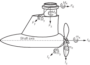
Figure 4.2.1 Pod co-ordinate system
2.2.2 Where
an engineering justification report is required, the following supporting
information is to be submitted:
- A Risk Assessment (RA) in accordance with Vol 2, Pt 1, Ch 3, 18 Risk Assessment (RA) is to be carried out, see
Vol 2, Pt 4, Ch 4, 2.1 Pod arrangement 2.1.1. The RA is to identify components where failure
could cause loss of all propulsion, steering capability or other Mobility systems or
Ship Type systems, and the proposed arrangements for preventing and mitigating the
effects of such a failure.
- Design standards and assumptions.
- Limiting operating parameters.
- A statement and evidence in respect of the anticipated reliability
of any components.
2.2.3 Recommended
installation, inspection, maintenance and component replacement procedures, see also
Vol 2, Pt 4, Ch 4, 4.1 Pod structure 4.1.2. This
is to include any in-water/underwater engineering procedures where
recommended by the pod manufacturer. See also
Vol 2, Pt 4, Ch 4, 5.5 Bearing lubrication system 5.5.7 and Vol 2, Pt 4, Ch 4, 8 Installation, maintenance and replacement procedures.
2.3 Pod internal atmospheric conditions
2.3.1 Machinery
and electrical equipment installed within the pod unit are to be suitable
for operation, without degraded performance, at the maximum anticipated
air temperature and humidity conditions within the pod unit with the
pod operating at its maximum continuous rating in sea water of not
less than 32°C after steady state operating conditions have been
achieved.
2.3.2 Precautions
are to be taken to prevent as far as reasonably practicable the possibility
of danger to personnel and damage to equipment arising from the development
of hazardous atmospheric conditions within the pod unit. Circumstances
that may give rise to these conditions are to be identified and the
counter measures taken are to be defined.
2.4 Global loads
2.4.1 The
overall strength of the podded propulsion unit structure is to be
based upon the maximum anticipated inservice loads, including, the
effects of ship manoeuvring and of ship motion, see
Table 3.2.1 Ship motions in Vol 1, Pt 5, Ch 3.
This is to include the effects of any pod to pod and/or pod to ship
hydrodynamic interference effects. The designer is to supply the following
maximum load and moment values to which the unit may be subjected
with a description of the operating condition at which they occur.
-
F
x, Force in the longitudinal direction;
-
F
y, Force in the transverse direction;
-
F
z, Force in the vertical direction including
self weight, in water, augmented by the ship’s pitch and heave
motion and flodded volume where applicable, see
Vol 2, Pt 4, Ch 4, 4.3 Direct calculations 4.3.3 and Vol 1, Pt 5, Ch 3 Local Design Loads;
-
M
x, moment at the slewing ring about the
pod unit’s global longitudinal axis;
-
M
y, moment at the slewing ring about the
pod unit’s global transverse axis;
-
M
z, moment at the slewing ring about the
pod unit’s vertical axis (maximum dynamic duty steering torque
on steerable pods).
The directions of the X, Y and Z axes, with the origin at the
centre of the slewing ring, are shown in Figure 4.2.1 Pod co-ordinate system.
2.4.2 Where
the maximum forces and moments defined in Vol 2, Pt 4, Ch 4, 2.4 Global loads 2.4.1 cannot be accurately calculated,
then an estimate of these loadings is to be stated together with an
assessment of the associated error tolerances for the sequences of
permitted design manoeuvres, see
Vol 2, Pt 4, Ch 4, 1.1 Application 1.1.7. Typically this will include
emergency astern manoeuvres, zig zag manoeuvres and pod interaction.
Such estimates are to be defined on a load versus pod angle basis.
In the case of pod to pod and/or pod to ship hydrodynamic interaction
effects, these must be defined for the most severely affected propulsor
including cases where pod units are capable of being independently
steered.
2.4.3 Where
control systems are installed to limit the operation of the podded
drive to defined angles at defined ship speeds, this information may
be taken into consideration when determining the pod unit loading.
2.4.4 Where
pod units are fixed about their Z axis, then maximum global loads,
to be used as the basis of the structural appraisal, are to be determined
for inflows in 5 degree increments between the extremes of anticipated
inflow angle during manoeuvring with ship at full speed and maximum
propeller thrust.
2.4.5 The
podded propulsor is to be capable of withstanding a blade root failure
due to fatigue occurring at the maximum rated output of the podded
propulsor without initiating a failure in other parts of the propulsor
system. After a blade failure, the podded propulsor is to be capable
of reduced power operation in accordance with the manufacturer's instructions.
2.5 Ice Class Requirements
|