
Section
14 Construction
14.1 Access arrangements
14.1.1 In
watertube boilers, manholes are to be provided in all drums of sufficient
size to allow access for internal examination and cleaning, and for
fitting and expanding the tubes. In the case of headers for water
walls, superheaters or economisers, and of drums which are too small
to permit entry, sight holes or mudholes sufficiently large and numerous
for these purposes are to be provided.
14.1.2 Cylindrical
boilers are to be provided, where possible with means for ingress
to permit examination and cleaning of the inner surfaces of plates
and tubes exposed to flame. Where the boilers are too small to permit
this there are to be sight holes and mudholes sufficiently large and
numerous to allow the inside to be satisfactorily cleaned.
14.1.3 Where
the cross tubes of vertical boilers are large, there is to be a sight
hole in the shell opposite to one end of each tube sufficiently large
to allow the tube to be examined and cleaned. These sight holes are
to be in positions accessible for that purpose.
14.1.4 Manholes
in cylindrical shells should preferably have their shorter axes arranged
longitudinally.
14.1.5 Doors
for manholes, mudholes and sight holes are to be formed from steel
plate or other approved construction, and all jointing surfaces are
to be machined.
14.1.6 Doors
of the internal type are to be provided with spigots which have a
clearance of not more than 1,5 mm all round, i.e. the axes of the
opening are not to exceed those of the door by more than 3 mm. The
width of the manhole gasket seat is to be not less than 16 mm.
14.1.7 Doors
of the internal type for openings not larger than 230 mm x 180 mm
need be fitted with one stud only, which may be forged integral with
the door. Doors for openings larger than 230 mm x 180 mm are to be
fitted with two studs or bolts. The strength of the attachment to
the door is to be not less than the strength of the stud or bolt.
14.1.8 The
crossbars or dogs for doors are to be of steel.
14.1.9 For
smaller circular openings in headers and similar fittings, an approved
type of plug may be used.
14.1.10 Circular flat cover plates may be fitted to raised circular manhole frames
not exceeding 400 mm diameter, and for an approved design pressure not exceeding 1,8
MPa.
14.1.11 External
circular flat cover plates are to be in accordance with a recognised
National Standard.
14.2 Torispherical and semi-ellipsoidal ends
14.2.2 Where
the difference in thickness is the same throughout the circumference,
the thicker plate is to be reduced in thickness by machining to a
taper for a distance not less than four times the offset, so that
the two plates are of equal thickness at the position of the circumferential
weld. A parallel portion may be provided between the end of the taper
and weld edge preparation; alternatively, if so desired, the width
of the weld may be included as part of the smooth taper of the thicker
plate.
14.2.3 The
thickness of the plates at the position of the circumferential weld
is to be not less than that of an unpierced cylindrical shell of seamless
or welded construction, whichever is applicable, of the same diameter
and material, see
Vol 2, Pt 8, Ch 1, 4.1 Minimum thickness
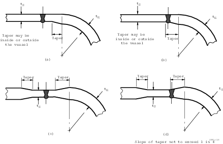
Figure 1.14.1 Typical attachments of dished ends to cylindrical shells
14.3 Hemispherical ends
14.3.1 Where
hemispherical ends are butt welded to cylindrical shells, the thickness
of the shell is to be reduced by taper to that of the end, and the
centre of the hemisphere is to be so located that the entire tapered
portion of the shell and the butt weld are within the hemisphere, see
Figure 1.14.2 Attachment of hemispherical end to cylindrical shell.
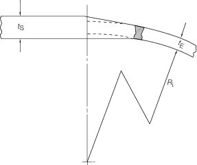
Figure 1.14.2 Attachment of hemispherical end to cylindrical shell
14.3.2 If
the hemispherical end is provided with a parallel portion, the thickness
of this portion is to be not less than that of a seamless or welded
shell, whichever is applicable, of the same diameter and material.
14.4 Welded-on flanges, butt welded joints and fabricated branch pieces
14.4.1 Flanges
may be cut from plates or may be forged or cast. Hubbed flanges are
not to be machined from plate. Flanges are to be attached to branches
by welding. Alternative methods of flange attachment will be subject
to special consideration.
14.4.2 The
types of welded-on flanges are to be suitable for the pressure, temperature
and service for which the branches are intended.
14.4.3 Flange
attachments and pressure-temperature ratings in accordance with materials
and design of recognised standards will be accepted.
14.4.4 Typical
examples of welded-on flange connections are shown in Figure 1.14.3 Typical examples of welded flange connections(a) to (f), and limiting
design conditions for the flange types are shown in Table 1.14.1 Limited design conditions for
flanges. In Figure 1.14.3 Typical examples of welded flange connections, t is
the minimum Rule thickness of the standpipe or branch.
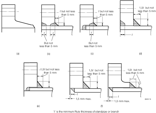
Figure 1.14.3 Typical examples of welded flange connections
Table 1.14.1 Limited design conditions for
flanges
Flange
type
|
Maximum
pressure
|
Maximum
temperature
|
Maximum
pipe o.d.
|
Minimum
pipe bore
|
|
|
|
°C
|
mm
|
mm
|
| (a)
|
Pressure-temperature ratings
to be in accordance with a recognised standard
|
No restriction
|
No restriction
|
No restriction
|
| (b)
|
Pressure-temperature ratings to be in accordance with a recognised
standard
|
No
restriction
|
168,3 for alloy
steels*
|
No
restriction
|
| (c)
|
Pressure-temperature ratings to be in accordance with a recognised
standard
|
No
restriction
|
168,3 for alloy
steels*
|
75
|
| (d)
|
Pressure-temperature ratings to be in accordance with a recognised
standard
|
425
|
No
restriction
|
No
restriction
|
| (e)
|
Pressure-temperature ratings to be in accordance with a recognised
standard
|
425
|
No
restriction
|
75
|
| (f)
|
Pressure-temperature ratings
to be in accordance with a recognised standard
|
425
|
No restriction
|
No restriction
|
| *No restriction for carbon steels
|
14.4.5 Welded-on
flanges are not to be a tight fit on the branch. The maximum clearance
between the bore of the flange and the outside diameter of the branch
is to be 3 mm at any point, and the sum of the clearances diametrically
opposite is not to exceed 5 mm.
14.4.6 Where
butt welds are employed in the attachment of flange type (a), or in
the construction of standpipes or branch pieces, the adjacent pieces
are to be matched at the bores. This may be effected by drifting,
roller expanding or machining, provided the pipe wall is not reduced
below the designed thickness. If the parts to be joined differ in
wall thickness, the thicker wall is to be gradually tapered to that
of the thinner at the butt joint.
14.4.7 Welding
may be carried out by means of the shielded metal arc, inert gas metal
arc, oxy-acetylene or other approved process, but in general, oxy-acetylene
welding is suitable only for flange type (a) and is not to be applied
to branches exceeding 100 mm diameter or 9,5 mm thick. The welding
is to be carried out in accordance with the appropriate paragraphs
of Vol 2, Pt 1, Ch 4 Requirements for Fusion Welding of Pressure Vessels and Piping.
14.4.8 Threaded
sleeve joints complying with Vol 2, Pt 7, Ch 1, 5.6 Socket weld joints 5.6.1 may be used on the steam and water piping of small
oil fired package boilers of the once through coil type, used for
auxiliary or domestic purposes, where the feed pump capacity limits
the output.
14.5 Welded attachments to pressure vessels
14.5.1 Unless
the actual thickness of the shell or end is at least twice that required
by calculation for a seamless shell or end, whichever is applicable,
doubling plates with well rounded corners are to be fitted in way
of attachments such as lifting lugs, supporting brackets and feet,
to minimise load concentrations on pressure shells and ends. Compensating
plates, pads, brackets and supporting feet are to be bedded closely
to the surface before being welded, and are to be provided with a
‘tell-tale’ hole not greater than 9,5 mm in diameter,
open to the atmosphere to provide for the release of entrapped air
during heat treatment of the vessel, or as means of indicating any
leakage during hydraulic testing and in service. See
Vol 2, Pt 1, Ch 4 Requirements for Fusion Welding of Pressure Vessels and Piping
14.5.3 Where
fillet welds are used to attach standpipes or set-in pads, there are
to be equal sized welds both inside and outside the vessel, see
Figure 1.14.4 Typical acceptable methods of attaching branches and pads(a) and (l). The leg
length of each of the fillet welds is to be not less than 1,4 times
the actual thickness of the thinner of the parts being joined.
14.6 Fitting of tubes in water tube boilers
14.6.1 The
tube holes in drums or headers are to be formed in such a way that
the tubes can be effectively tightened in them. Where the tube ends
are not normal to the tube plates, there is to be a neck or belt of
parallel seating of at least 13 mm in depth, measured in a plane through
the axis of the tube at the holes. Where the tubes are practically
normal to their plates, this parallel seating is to be not less than
9,5 mm in depth.
14.6.2 Tubes
are to be carefully fitted in the tube holes and secured by means
of welding, expanding and belling or by other approved methods. Tubes
are to project through the neck or belt of parallel seating by at
least 6 mm and where they are secured from drawing out by means of
bellmouthing only, the included angle of belling is to be not less
than 30°.
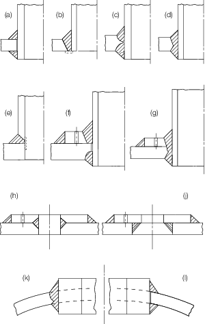
Figure 1.14.4 Typical acceptable methods of attaching branches and pads
|