
Section
4 Design of gearing
4.1 Symbols
4.1.1 For the
purposes of this Chapter the following symbols apply:
|
a
|
= |
centre
distance, in mm |
|
|
= |
Note: unless otherwise
specified, b is to be taken as the lesser value of b
1or b
2.
|
|
|
= |
In the case of double
helical gears b = 2b
B where b
B is the width of one helix.
|
|
d
|
= |
reference
diameter, in mm |
|
d
a
|
= |
tip diameter, in mm |
|
d
an
|
= |
virtual tip diameter, in mm |
|
d
b
|
= |
base diameter, in mm |
|
d
bn
|
= |
virtual base diameter, in mm |
|
d
en
|
= |
virtual diameter to the highest point of single tooth pair contact,
in mm |
|
d
f
|
= |
root diameter, in mm |
|
d
fn
|
= |
virtual root diameter, in mm |
|
d
n
|
= |
virtual reference diameter, in mm |
|
d
s
|
= |
shrink diameter, in mm |
|
d
w
|
= |
pitch circle diameter, in mm |
|
f
ma
|
= |
tooth flank misalignment due to manufacturing errors, in μm |
|
f
pb
|
= |
maximum base pitch deviation of wheel, in μm |
|
f
Sh
|
= |
tooth flank misalignment due to wheel and pinion deflections,
in μm |
|
f
Sho
|
= |
intermediary factor for the determination of f
Sh
|
|
g
α
|
= |
length of line of action for external gears, in mm: |
|
h
|
= |
total
depth of tooth, in mm |
|
h
ao
|
= |
basic rack addendum of tool, in mm |
|
h
F
|
= |
bending moment arm for root stress, in mm |
|
h
w
|
= |
sum of actual tooth addenda of pinion and wheel, in mm |
|
m
n
|
= |
normal module, in mm |
|
q
|
= |
machining
allowances, in mm |
|
q'
|
= |
intermediary
factor for the determination of C
γ
|
|
u
|
= |

|
|
v
|
= |
linear
speed at pitch circle, in m/s |
|
x
|
= |
addendum
modification coefficient |
|
y
α
|
= |
running in allowance, in μm |
|
y
β
|
= |
running in allowance, in μm |
|
z
n
|
= |
virtual number of teeth = 
|
|
C
γ
|
= |
tooth mesh stiffness (mean total mesh stiffness per unit face
width), in N/mm μm |
|
F
t
|
= |
nominal tangential tooth load, in N |
|
F
β
|
= |
total tooth alignment deviation (maximum value specified), in μm |
|
F
βx
|
= |
actual longitudinal tooth flank deviation before running in,
in μm |
|
F
βy
|
= |
actual longitudinal tooth flank deviation after running in,
in μm |
|
Hv |
= |
Vickers hardness
number |
|
K
Fα
|
= |
transverse load distribution factor |
|
K
Fβ
|
= |
longitudinal load distribution factor |
|
K
Hα
|
= |
transverse load distribution factor |
|
K
Hβ
|
= |
longitudinal load distribution factor |
|
K
vα
|
= |
dynamic factor for spur gears |
|
K
vβ
|
= |
dynamic factor for helical gears |
|
K
γ
|
= |
load sharing factor |
|
P
|
= |
transmitted
power, in kW |
|
P
r
|
= |
radial pressure at shrinkage surface, in N/mm2
|
|
P
ro
|
= |
protuberance of tool, in mm |
|
R
a
|
= |
surface roughness − arithmetical mean deviation (C.L.A.)
as determined by an instrument having a minimum wavelength cut-off
of 0,8 mm and for a sampling length of 2,5 mm, in μm |
|
S
pr
|
= |
residual undercut left by protuberance in mm |
|
S
F min
|
= |
minimum factor of safety for bending stress |
|
S
Fn
|
= |
tooth root chord in the critical section, in mm |
|
S
H min
|
= |
minimum factor of safety for Hertzian contact stress |
|
S
R
|
= |
rim thickness of gears, in mm |
|
Y
B
|
= |
rim thickness factor |
|
Y
R rel T
|
= |
relative surface finish factor |
|
Y
S
|
= |
stress correction factor |
|
Y
ST
|
= |
stress correction factor (relevant to the dimensions of the
standard reference test gears) |
|
Y
δ rel T
|
= |
relative notch sensitivity factor |
|
Z
E
|
= |
material elasticity factor |
|
Z
R
|
= |
surface finish factor |

|
= |
contact ratio factor |
|
αen
|
= |
pressure
angle at the highest point of single tooth contact, in degrees |
|
αn
|
= |
normal
pressure angle at reference diameter, in degrees |
|
αt
|
= |
transverse
pressure angle at reference diameter, in degrees |
|
αtw
|
= |
transverse
pressure angle at pitch circle diameter, in degrees |
|
αF en
|
= |
angle for application of load at the highest point of single
tooth contact, in degrees |
|
β |
= |
helix angle
at reference diameter, in degrees |
|
βb
|
= |
helix
angle at base diameter, in degrees |
|
γ |
= |
intermediary
factor for the determination of f
Sh
|
 α
α
|
= |
transverse
contact ratio |
 α
n
α
n
|
= |
virtual transverse contact ratio |
 β
β
|
= |
overlap
ratio |
 γ
γ
|
= |
total
contact ratio |
|
ρao
|
= |
tip
radius of tool, in mm |
|
ρc
|
= |
relative
radius of curvature at pitch point, in mm |
|
ρF
|
= |
tooth
root fillet radius at the contact of the 30o tangent, in
mm
|
|
σy
|
= |
yield
or 0,2 per cent proof stress, in N/mm2
|
|
σB
|
= |
ultimate
tensile strength, in N/mm2
|
|
σF
|
= |
bending
stress at tooth root, N/mm2
|
|
σF lim
|
= |
endurance limit for bending stress in N/mm2
|
|
σFP
|
= |
allowable
bending stress at the tooth root, in N/mm2
|
|
σH
|
= |
Hertzian
contact stress at the pitch circle, in N/mm2
|
|
σH lim
|
= |
endurance limit for Hertzian contact stress, in N/mm2
|
|
σHP
|
= |
allowable
Hertzian contact stress, in N/mm2
|
Subscript:
Note
a and z are considered positive
for both external and internal gearing for the purposes of these calculations.
4.2 Tooth form
4.2.1 The tooth
profile in the transverse section is to be of involute shape, and
the roots of the teeth are to be formed with smooth fillets of radii
not less than 0,25 m
n.
4.2.2 All sharp
edges left on the tips and ends of pinion and wheel teeth after hobbing
and finishing are to be removed.
4.3 Tooth loading factors
4.3.1 For values
of application factor, K
A, see
Table 1.4.1 Values of K
A
.
Table 1.4.1 Values of K
A
| Main
and auxiliary gears
|
K
A
|
| Main propulsion - electric motor or
gas turbine, reduction gears
|
1,15
|
| Main propulsion - diesel engine
reduction gears:
|
|
| Hydraulic coupling or equivalent on
input
|
1,10
|
| High elastic coupling on input
|
1,30
|
| Other coupling
|
1,50
|
| Auxiliary Gears:
|
|
| Electric, gas turbine and diesel
engine drives with hydraulic coupling or equivalent on input
|
1,00
|
| Diesel engine drives with high elastic
coupling on input
|
1,20
|
| Diesel engine drives with other
couplings
|
1,40
|
4.3.2 Load sharing
factor, K
γ. When a gear drives two or
more mating gears where the total transmitted load is not evenly distributed
between the individual meshes, a factor, K
γ,
is to be applied. K
γ is defined as the
ratio between the maximum load through an actual path and the evenly
shared load. This is to be determined by measurements. Where a value
cannot be determined in such a way, the values in Table 1.4.2 Values of K
y
may be considered:
Table 1.4.2 Values of K
y
|
|
K
y
|
| Spur Gear
|
1,0
|
| Epicyclic Gears
|
|
| Up to 3 planetary gears
|
1,0
|
| 4 planetary gears
|
1,2
|
| 5 planetary gears
|
1,3
|
| 6 planetary gears and over
|
1,4
|
4.3.3
Dynamic
factor, K
V, is to be calculated as
follows when all the following conditions are satisfied:
- spur gears (β = 0°) and helical gears with β ≤
30°
- pinion with relatively low number of teeth, z1 <
50
- solid disc wheels or heavy steel gear rim
Or this method may also be applied to all types of gears if:
And to helical gears where β > 30°
-
For spur gears and
for helical gears with ∊β ≥ 1:
Where K
A
F
t/b is less than 100 N/mm, the value 100 N/mm is to be used.
Numerical values for the factor K
1 are to
be as specified in the Table 1.4.3 Values of K
1
Table 1.4.3 Values of K
1
|
|
K
1
ISO accuracy Grade
|
|
|
3
|
4
|
5
|
6
|
7
|
8
|
| Spur Gears
|
2,1
|
3,9
|
7,5
|
14,9
|
26,8
|
39,1
|
| Helical Gears
|
1,9
|
3,5
|
6,7
|
13,3
|
23,9
|
34,8
|
-
For all accuracy grades the factor K
2 is
to be in accordance with the following:
- for spur gears K
2 = 0,0193
- for helical gears K
2 = 0,0087
Factor K
3 is to be in accordance with
the following:
-
For helical gears
with overlap ratio ∊β < 1, the value K
v is to be determined by linear interpolation between values
determined for spur gears (K
vα) and helical
gears (K
vβ) in accordance with:

K
vα is the K
v value
for spur gears, in accordance with Pt 11, Ch 1, 4.3 Tooth loading factors 4.3.3
K
vβ is the K
v value
for helical gears, in accordance with Pt 11, Ch 1, 4.3 Tooth loading factors 4.3.4.(b)
4.3.5
Longitudinal
load distribution factors, K
Hβ and K
Fβ:
Calculated values of K
Hβ >
2 are to be reduced by improved accuracy and helix correction as necessary:
where
|
F
β
y
|
= |
F
β
x − y
β and
|
|
F
β
x
|
= |
1,33 f
Sh + f
ma
|
|
f
ma
|
= |
 F
β at the design stage, or
F
β at the design stage, or
|
|
f
ma
|
= |
 F
β where helix correction
has been applied
F
β where helix correction
has been applied
|
|
f
Sh
|
= |

|
where
|
F
Sho
|
= |
23γ10−3 μm mm/N for gears without
helix correction or crowning and without end relief, or
|
|
|
= |
12γ10−3 μm mm/N for gears without helix correction but with crowning, See Note 1
|
|
|
= |
16γ10−3 μm mm/N for gears without helix correction but with end
relief, where
|
|
γ |
= |
 for single helical and spur gears for single helical and spur gears
|
|
|
= |
 for double helical gears for double helical gears
|
The following minimum values are applicable, these also being
the values where helix correction has been applied:
|
f
Sho
|
= |
10 x 10−3 μm mm/N for helical gears, or
|
|
|
= |
5 x 10⁻³ μm
mm/N for spur gears
|
For through-hardened steels and surface hardened
steels running on through-hardened steels:
|
yβ
|
= |
 up to an upper limit value of up to an upper limit value of
|
|
yβ
|
= |
 m, and m, and
|
For surface hardened steels, when
|
y
β
|
= |
0,15F
β
x up to an upper
limit value of
|
where
|
|
= |

|
Note
1.
 is to be taken as the smaller of is to be taken as the smaller of 
Note
2. For double helical gears  is to be substituted for b in the equation
for n. is to be substituted for b in the equation
for n.
4.3.6
Transverse
load distribution factors, K
H
α and K
F
α
-
Values K
Hα and K
Fα for gears with total
contact ratio ∊γ ≤ 2
-
Values K
Hα and K
Fα for gears with total
contact ratio ∊γ > 2
Limiting conditions for KHα:
If  when calculated in accordance with (a) or (b), then when calculated in accordance with (a) or (b), then 
If K
Hα< 1 when calculated in
accordance with (a) or (b), then K
Hα =1
Limiting conditions for K
Fα:
If  when calculated in accordance with (a) or (b), then when calculated in accordance with (a) or (b), then 
If K
Fα< 1 when calculated in
accordance with (a) or (b), then K
Fα=1
When tip relief is applied f
pb is to
be half of the maximum specified value:

|
= |
for through-hardened steels, when |

|
= |
and |
|
y
α
|
= |
0,075 f
pb for surface hardened steels,
when
|
y
α ≤ 3 μm
When pinion and wheel are manufactured from different
materials:
Note Tip relief is to take the form of either tip and root
relief on the pinion, or tip relief on pinion and wheel.
4.3.7
Tooth
mesh stiffness, C
γ:
where
|
|
= |

|
For internal gears Z
n2 = ∞
Other calculation methods for C
γ will
be specially considered.
4.4 Tooth loading for surface stress
4.4.1 The Hertzian contact stress, σH, at
the pitch circle is not to exceed the allowable Hertzian contact stress, σHP.
and
 for the pinion/wheel combination for the pinion/wheel combination
where
Z
∊, contact ratio factor is to be calculated as follows:
for helical
gears:
for spur gears
where:
The peak to valley roughness determined for the pinion
R
Z1 and for the wheel R
Z2 are mean values for the peak to valley roughness R
z measured on several tooth flanks.

relative radius of curvature:
where:
For internal gears, d
b has a negative sign.
If R
a, the surface roughness of the tooth flanks is given then the following
approximation may be applied:
C
ZR is to be taken from Table 1.4.4 Values of C
ZR
.
For values of Z
x, see
Table 1.4.5 Values of Zx
σH lim,
see
Table 1.4.6 Values of endurance limit for
Hertzian contact stress, σ H lim
S
H min,
see
Table 1.4.7 Factors of safety
Table 1.4.4 Values of C
ZR
|
σH lim
|
CZR
|
|
σH lim
< 850 N/mm2
|
0,150
|
| 850 N/mm2 ≤ σH
lim
≤ 1200 N/mm2
|
=0,32-0,0002∙σH lim
|
|
σH lim
>1200 N/mm2
|
0,080
|
Table 1.4.5 Values of Zx
| Pinion heat treatment
|
Z
x
|
| Carburised and
induction-hardened
|
m
n ≤ 10
|
1,00
|
| 10 < m
n < 30
|
1,05 - 0,005m
n
|
| 30 ≤ m
n
|
0,9
|
|
|
|
|
| Nitrided
|
m
n < 7,5
|
1,00
|
| 7,5 < m
n<30
|
1,08 - 0,005mn
|
| 30 ≤ m
n
|
0,75
|
|
|
|
|
| Through-hardened
|
All modules
|
1,00
|
Table 1.4.6 Values of endurance limit for
Hertzian contact stress, σ H lim
| Heat treatment
|
|
| Pinion
|
Wheel
|
|
| Through-hardened
|
Through-hardened
|
0,46σB2 + 255
|
| Surface-hardened
|
Through-hardened
|
0,42σB2 + 415
|
| Carburised, nitrided or
induction-hardened
|
Soft bath nitrided
(tufftrided)
|
1000
|
| Carburised, nitrided or
induction-hardened
|
Induction-hardened
|
0,88HV
2 + 675
|
| Carburised or nitrided
|
Nitrided
|
1300
|
| Carburised
|
Carburised
|
1500
|
Table 1.4.7 Factors of safety
|
|
S
H min
|
S
F min
|
| Main propulsion gears
|
1,40
|
1,80
|
| Auxiliary gears
|
1,15
|
1,40
|
4.5 Tooth loading for bending stress
4.5.1 The bending
stress at the tooth root, σF is not to exceed the
allowable tooth root bending stress σFP:
Note If b
1 and b
2 are
not equal to the load bearing width of the wider face taken is not
to exceed that of the smaller plus 2m
n.
For values of S
F min, see
Table 1.4.7 Factors of safety
Stress correction factor Y
ST =
2.
4.5.2
Tooth
form factor, Y
F:
where h
F, αFen and S
Fn are shown in Figure 1.4.1 Normal tooth section.
E, h
ao, αn, S
pr and ρao are shown
in Figure 1.4.2 External tooth forms.
where
|
d
an
|
= |
d
n + d
a - d
|
|
|
= |

|
where
|
αen
|
= |

|
|
|
= |

|
Table 1.4.8 Values of endurance limit for
bending stress, σ F lim
| Heat treatment
|
σF lim N/mm2
|
| Through-hardened carbon steel
|
0,09σB + 150
|
| Through-hardened alloy steel
|
0,1σB + 185
|
| Soft bath nitrided
(Tufftrided)
|
330
|
| Induction hardened
|
0,35 HV + 125
|
| Gas nitrided
|
390
|
| Carburised A
|
450
|
| Carburised B
|
410
|
Note
1. A is applicable for Cr Ni Mo
carburising steels.
Note
2. B is applicable for other carburising
steels.
|
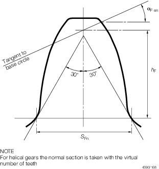
Figure 1.4.1 Normal tooth section
4.5.3 For internal
tooth forms the form factor is calculated, as an approximation, for
a substitute gear rack with the form of the basic rack in the normal
section, but having the same tooth depth as the internal gear:
where αF en is taken as being equal
to αn
d
en2 is calculated as d
en for external gears, and
4.5.4
Stress
concentration factor, Y
s
where
|
L
|
= |

|
|
q
s
|
= |

|
when q
s < 1 the value of Y
s is to be specially considered.
The formula for Y
s is applicable to external gears with αn =
20o but may be used as an approximation for other pressure
angles and internal gears.
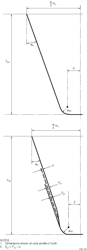
Figure 1.4.2 External tooth forms
4.5.5
Helix
angle factor Y
β
but
Y
b ≥ 1
− 0,25 β ≥ 0,75
4.5.6
Rim
thickness factor, Y
B
Factor Y
B is to be determined as follows:
-
For external gears
If S
R/h ≥ 1,2 then Y
B = 1
If 0,5 < S
R/h <1,2 then 
where
|
S
R
|
= |
rim thickness of external gears, mm |
The case S
R/h ≤ 0,5 is
to be avoided.
-
For internal gears
If S
R/mn ≥ 3,5 then Y
B = 1
If 1,75 < S
R/mn < 3,5
then
Where
S
R = rim thickness
of internal gears, mm
The case S
R/mn ≤ 1,75
is to be avoided.
4.5.7
Deep
tooth factor Y
DT
The deep tooth factor, Y
DT, adjusts
the root stress to take into account high precision gears and contact
ratios within the range of virtual contact ratio 2,05 ≤ ∊αn ≤ 2,5 where:
Factor Y
DT is to be determined
from Table 1.4.9 Values of deep tooth factor,
Y
DT
:
Table 1.4.9 Values of deep tooth factor,
Y
DT
|
|
Y
DT
|
| ISO Accuracy Grade ≤ 4 and
∊αn > 2,5
|
0,7
|
| ISO Accuracy Grade ≤ 4 and 2,05 <
∊αn ≤ 2,5
|
2,366 – 0,666⋅ ∊αn
|
| In all other cases
|
1,0
|
4.5.8
Relative
notch sensitivity factor, Yδ rel T
ρ’ = slip-layer thickness is to be taken
from Table 1.4.10 Slip-layer thickness, ρ’
Table 1.4.10 Slip-layer thickness, ρ’
| Material
|
ρ’, (mm)
|
| Case
hardened steels, flame or induction hardened steels
|
0,0030
|
| Through-hardened steels, yield point
R
e =
|
500 N/mm2
|
0,0281
|
|
|
600 N/mm2
|
0,0194
|
|
|
800 N/mm2
|
0,0064
|
|
|
1000 N/mm2
|
0,0014
|
| Nitrided
steels
|
0,1005
|
Note The given values of ρ’ can be interpolated for values of
R
e not stated above
|
4.5.9
Relative
surface finish factor, Y
R rel T
|
Y
R rel T
|
= |
1,674 − 0,529 (6R
a + 1)0,1 for
through-hardened, carburised and induction hardened steels, and
|
| = |
4,299 − 3,259 (6R
a +
1)0,005 for nitrided steels.
|
4.5.10
Size
factor, Y
x
|
Y
x
|
= |
1,00, when m
n ≤ 5
|
| = |
1,03 − 0,006m
n for
through-hardened steels
|
| = |
0,85, when m
n ≥
30
|
| = |
1,05 − 0,01 m
n for
surface-hardened steels
|
| = |
0,80, when m
n ≥
25.
|
4.5.11
Design
factor, Y
D
|
Y
D
|
= |
0,83 for gears treated with a controlled shot peening process |
| = |
1,5 for idler gears |
| = |
1,25 for shrunk on gears, or |
| = |

|
| = |
1,00 or any combination of the
above — e.g. Y
D= (0,83 × 1,5)
for an idler gear treated with a controlled shot peening process.
|
4.6 Factors of safety
4.7 Design of enclosed gear shafting
4.7.1 The following
symbols apply:
P in kW and R in rpm, see
Pt 11, Ch 1, 1.2 Power ratings 1.2.1.
|
L
|
= |
span
between shaft bearing centres, in mm |
|
σn
|
= |
normal
pressure angle at the gear reference diameter, in degrees |
|
β |
= |
helix angle
at the gear reference diameter, in degrees |
|
d
w
|
= |
pitch circle diameter of the gear teeth, in mm |
|
σu
|
= |
specified
minimum tensile strength of the shaft material, in N/mm2
|
Note Numerical value used for σu is not to
exceed 800 N/mm2 for gear and thrust shafts and 1100 N/mm2for quill shafts.
4.7.2 This sub-Section
is applicable to the main and ancillary transmission shafting, enclosed
within the gearcase.
4.7.3 The diameter
of the enclosed gear shafting adjacent to the pinion or wheel is to
be not less than the greater of d
b or d
t, where:
where
|
S
b
|
= |
45 + 0,24 (σu — 400) and
|
|
S
s
|
= |
42 + 0,09 (σu — 400).
|
4.7.4 For the
purposes of the above it is assumed that the pinion or wheel is mounted
symmetrically spaced between bearings.
4.7.5 Outside
a length equal to the required diameter at the pinion or wheel, the
diameter may be reduced, if applicable, to that required for d
t.
4.7.6 For bevel
gear shafts, where a bearing is located adjacent to the gear section,
the diameter of the shaft is to be not less than d
t.
Where a bearing is not located adjacent to the gear the diameter of
the shaft will be specially considered.
4.7.7 The diameter
of quill shaft (not axially constrained and subject only to external
torsional loading) is to be not less than given by the following formula:
Diameter of quill shaft =

4.7.8 Where
a shaft, located within the gearcase, is subject to the main propulsion
thrust, the diameter at the collars of the shaft transmitting torque,
or in way of the axial bearing where a roller bearing is used as a
thrust bearing, is to be not less than 1,1 d
t.
For thrust bearings located outside the gearcase see
Pt 11, Ch 2, 2 Particulars to be submitted.
4.8 Gear wheels
4.8.1 In general,
arrangements are to be made so that the interior structure of the
wheel may be examined. Alternative proposals will be specially considered.
4.9 External shafting and components
4.10 Clutch actuation
4.10.1 Where
a clutch is fitted in the transmission, normal engagement shall not
cause excessive stresses in the transmission or the driven machinery.
Inadvertent operation of any clutch is not to produce dangerously
high stresses in the transmission or driven machinery.
4.11 Gearcases
4.11.1 Gearcases
and their supports are to be designed sufficiently stiff such that
misalignment at the mesh due to movements of the external foundations
and the thermal effects under all conditions of service do not disturb
the overall tooth contact.
4.11.2 Inspection
openings are to be provided at the peripheries of gearcases to enable
the teeth of pinions and wheels to be readily examined. Where the
construction of gearcases is such that sections of the structure cannot
be readily be moved for inspection purposes, access openings of adequate
size are also to be provided at the ends of the gearcases to permit
examination of the structure of the wheels. Their attachment to the
shafts is to be capable of being examined by removal of bearing caps
or by equivalent means.
4.11.3 For
gearcases fabricated by fusion welding the carbon content of the steels
should generally not exceed 0,23 per cent. Steels with higher carbon
content may be approved subject to satisfactory results from weld
procedure tests.
4.11.4 Gearcases
are to be stress relieved upon completion of all welding.
4.11.5 Gearcases
manufactured from material other than steel will be considered upon
full details being submitted.
4.12 Backlash
4.12.1 The
normal backlash between any pair of gears should not be less than:
4.13 Alignment
4.13.1 Reduction
gears with sleeve bearings, for main and auxiliary purposes are to
be provided with means for checking the internal alignment of the
various elements in the gearcases.
4.13.2 In the
case of separately mounted reduction gearing for main propulsion,
means are to be provided by the gear manufacturer to enable the Surveyors
to verify that no distortion of the gearcase has taken place, when
chocked and secured to its seating on board the craft.
|