
Section
8 Building tolerances and associated repairs
8.1 Tolerances - General
8.1.2 Tolerances
to be used for constructional misalignment for all materials are to
be discussed between Owners/Builders and the Surveyor and acceptable
Standards agreed subject to the requirements of this Chapter or National
Authority requirements where applicable. The permitted degree of inaccuracy/misalignment
will vary according to whether the defect is:
-
In primary structure.
-
In secondary structure.
-
Aesthetically pleasing.
8.2 Raw material surface tolerances
8.2.1 The surface
cleanliness of steel/aluminium alloy materials in preparation for
painting is to be in accordance with National or paint Manufacturer's
Standards.
8.2.2 Where approved
corrosion control coatings are to be used the quality of the surface
treatment is to be in accordance with the grade specified in the approval
documents.
8.3 Surface defects
8.3.1 The limits
of depth and extent of surface defects on plate, cast or forged materials
in relation to the material plate thickness are shown in Table 1.8.1 Limits of surface defects.
8.3.2 Defects
are to be made good by grinding only subject to the plate thickness
not being reduced by more than seven per cent of the nominal thickness
or 3 mm whichever is the lower, and the area involved not exceeding
two per cent of the surface area.
8.3.4 Where the
depth of the deepest imperfection exceeds 20 per cent of the nominal
thickness, or the defective area exceeds two per cent of the total
surface area, such areas are to be cropped and replaced. See
Pt 3, Ch 1, 8.5 Part replacement of plates.
8.3.5 Complete
removal of the defects is to be verified by suitable non-destructive
examination techniques and after welding the repair is to be proved
free from further defects. The complete removal of defects is to be
verified by nondestructive examination in accordance with the requirements
specified in Ch 13 Requirements for Welded Construction of the Rules
for Materials.
8.3.6 Care is
to be taken in the repair of defects in higher tensile steel, and
aluminium alloy materials. Low hydrogen electrodes with similar properties
to the higher tensile steel are to be used with preheating as necessary.
Aluminium alloys are to be heat treated after repair, see
Pt 7, Ch 2, 3 Procedures for welded construction.
Table 1.8.1 Limits of surface defects
| Normal
thickness of material (mm)
|
Maximum permissible depth of defect (mm)
|
| Area
affected - Unlimited
|
Area
affected ≤ 5% of Surface
|
| <
8
|
0,2
|
0,4
|
| 8 to
25
|
0,3
|
0,5
|
| 25 to
40
|
0,4
|
0,6
|
| ≥ 40
|
0,5
|
0,8
|
Note
1. Defects are to be measured after shot
blasting or plate cleaning.
Note
2. The depth of the deepest imperfection
is to be considered.
Note
3. Defects not exceeding the limits shown
need not be repaired.
Note
5. Defects exceeding the above limits are
to be repaired.
Note
6. Crack-like defects are always to be
repaired irrespective of their depth.
|
8.4 Plate laminations
8.4.1 Plates
in which laminations are suspected or detected are to be ultrasonically
tested to determine the full extent of such laminations.
8.4.2 Where laminations
are confined to the plate edge, are less than 300 mm long and whose
penetration is not more than half the plate thickness, then the defect
may be chipped or ground out and rebuilt with weld material.
8.4.3 Where laminations
are isolated, located near to the plate surface, and where the total
area of the defect does not exceed two per cent of the surface area
of the plate, the defect may be repaired as in Pt 3, Ch 1, 8.4 Plate laminations 8.4.2.
8.4.5 Complete
removal of the defect is to be verified by non-destructive examination,
and after welding, the repair is to be proved free from further defects.
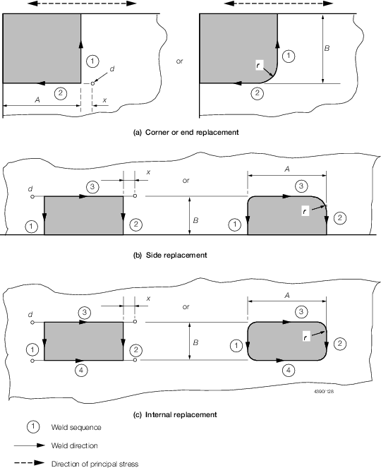
8.5 Part replacement of plates
8.6 Structural misalignment and fit (steel and aluminium)
8.6.3 Welding
defects are generally to be dealt with in accordance with Ch 13 Requirements for Welded Construction of the Rules for Materials. Limits
for weld undercut and remedial action to be taken depend on plate
thickness and are to be discussed and agreed by the Builder and the
Surveyor prior to commencement of repairs.
8.7 Post welding plate deformation
8.7.3 Local heating
of steel is not to exceed 900oC (red heat) when flame straightening
is employed.
8.7.4 Local heating
of aluminium alloys is not to be carried out. All repairs are to be
by renewal of plating.
Table 1.8.2 Part replacement of plates
| A x B
|
Parts
to be replaced
|
Shell,
strength deck, tank top, top and bottom strakes of longitudinal
bulkheads
|
Elsewhere
|
| End and
corner of plate
|
1000 x
1000
|
1000 x
300
|
| Side of
plate
|
1000 x
300
|
1000 x
300
|
| Insert
|
1000 x
300
|
1000 x
300
|
| Line of plate replacement to be not less than 100
from extreme edge of defect.
|
| All dimensions are in mm.
|
|
Note
1. All dimensions are minimum.
Note
2. Rolling direction of replaced plate to
be the same as that of the parent plate.
Note
3. Minimum distance from outermost defect
to line of weld – 100 mm.
|
Note
4. Dimensions in millimetres:
|
d
|
= |
1,5 x plate thickness with minimum 6 and maximum
20 |
|
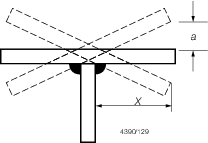
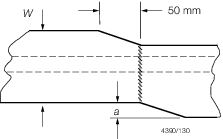
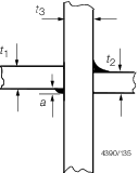
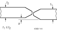
Table 1.8.3 Structural misalignment and fit
(steel and aluminium)
| Joint
|
Location
|
Acceptable dimensions (mm)
|
Remedial action
|
|
Fabricated frames
|
a ≤ ± 0,03 x
|
a > ± 0,03 x
|
Reject
|
| Beams,
girders and longitudinals
|
|
|
|
|
Butt
welded face flats primary structure
|
a ≤ 0,03W(max 6 mm)
|
a > 0,03W
|
Reject
|
| Secondary structure
|
a ≤ 0,04W (max 8 mm)
|
a > 0,04W
|
Reject
|
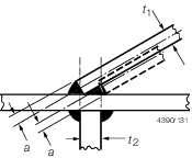
|
Obtuse
angle fillet weld
|
a ≤ t
1/2
|
a > t
1/2
|
Reject
|
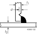
|
All
areas
|
d ≤ 0,1t
1 (max 0,8 mm)
|
d > 0,1t
1
|
Repair
by welding or grinding depends on thickness ‘t
1’ in accordance with 8.3
|
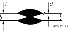
|
All
areas
|
d ≤ 0,1t
(max 0,8 mm)
|
d > 0,1t
|
As
above
|
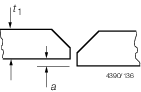
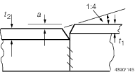
Table 1.8.4 Structural misalignment and fit
(steel and aluminium)
| Joint
|
Location
|
Permitted
misalignment
|
Remedial action
|
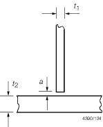
|
All
areas (Continuous fillet weld)
|
a (mm)
|
a (mm)
|
Increase weld leg length by ‘a’
|
|
|
0,25t
1 to 0,5t
1 (t
1 max = 5 mm)
|
| <
0,25t
1 (a max = 1 mm)
|
0,5t
1 to t
1 (t
1 max = 15 mm)
|
Vee material to +/–45o.
Fit backing strip and weld. Remove backing strip and complete weld. 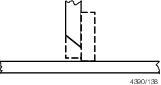
|
|
a > t
1
|
Realign and
replace
|
| All
areas (intermittent weld)
|
< 0,25t
1
|
0,25 to
0,5t
1 (t
1 max = 3 mm)
|
Increase
weld lengths by 50%
|
| 0,25t
1 to 0,5t
1 (t
1 max = 5 mm)
|
Continuous
weld
|
|
a > t
1
|
As for
continuous weld above
|
|
Strength
members
|
a ≤ t
2/3
|
t
2/3 ≤ a ≤ t
1/2
|
Increase
weld leg length of welds by 10%
|
| Others
|
a ≤ t
2/2
|
a > t
2/2
|
Realign
|
| Higher
tensile steel joint in designated critical areas
|
a ≤ t
3/3
|
a > t
3/3
|
Realign
|
|
Strength
members
|
a ≤ 0,15t
1(max 3,0 mm)
|
a > 0,15t
1
|
Realign
|
| Others
|
a ≤ 0,2t
1 (max 3,0 mm)
|
a > 0,2t
1
|
Realign
|
|
All
areas
|
a in accordance with weld procedure
|
a ≤ t
1
|
Build one
side of butt until a in accordance with weld procedure.
|
|
a >t
1 (max 10 mm)
|
Cut back 150 mm and fit insert
plate
|
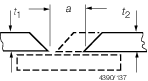
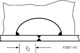
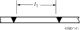
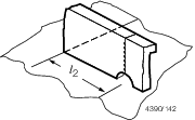
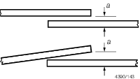
Table 1.8.5 Structural misalignment and fit
(steel and aluminium)
| Joint
|
Location
|
Acceptable dimensions (mm)
|
Remedial action
|
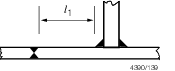
|
All
|
 1 ≥ 40 mm
|
–
|
Adjust to
suit
|
|
All
|
 2 ≥ 20 mm
|
–
|
Adjust to
suit
|
|
All
|
 1 > 50 mm
|
 1 < 30 mm
|
Treat as
an insert
|
|
All
|
 2 ≥ 20 mm
|
 2 < 15 mm
|
Adjust to
suit
|
|
All
|
a ≤ 1,0
|
a < 5
|
Increase weld leg length by actual ‘a’
|
| All
|
a ≤ 1,0
|
a ≤ 5
|
Adjust to suit
|
|
Strength members
|
a ≤ 0,15t
1 (max 3,0 mm)
|
a > 0,15t
1
|
Reject
|
| Other
|
a ≤ 0,2t
1 (max 3,0 mm)
|
a > 0,2t
1
|
Reject
|
|
All
|
For
angle or tee longitudinal a ≤ 0,2t
1
|
a > 0,2t
1
|
Reject
|
| For offset bulb
longitudinal a ≤ 0,2t
2
|
a > 0,2t
2
|
Reject
|
Table 1.8.6 Plate deformation limits
| Position
|
s/t
|
δp/s
|
| in
0,6L amidship
|
≤ 80
|
1/100
|
|
|
> 80
|
1/75
|
| Remainder
|
all
|
1/50
|
where
|
s
|
= |
stiffener spacing, in mm |
|
t
|
= |
plating thickness, in mm |
|
δp
|
= |
panel deflection, in mm |
|
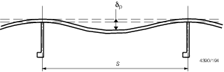
Figure 1.8.1 Measurement of plate deformation
|