
Section
5 Impact loads
5.1 Impact pressure for displacement mode
5.1.2 The bottom
shell impact pressure due to bottom slamming, is given by the following
expression:
|
Φdh
|
= |
0,09
at L
WL from aft end of L
WL
|
| = |
0,18 at 0,9L
WL from aft end of L
WL
|
| = |
0,18 at 0,8L
WL from aft end of L
WL
|
| = |
0,0 between aft end of L
WL and 0,5L
WL from aft end of L
WL
|
|
L
WL
|
= |
waterline length, in metres, see
Pt 5, Ch 2, 2.1 Parameters to be used for the determination of load and design criteria 2.1.19
|
|
V
|
= |
allowable speed, in knots, see
Pt 5, Ch 2, 2.1 Parameters to be used for the determination of load and design criteria 2.1.2. |
Intermediate values to be determined by linear interpolation. T
x is taken to be the draught T, as
defined in Pt 3, Ch 1, 6 Definitions, but need
not be taken greater than 0,08L
WL.
P
dh at 0,9L
WL and 0,8L
WL from aft end of L
WL need not be taken
greater than P
f at L
WL from
aft end of L
WL as defined in Pt 5, Ch 2, 5.4 Forebody impact pressure for displacement mode 5.4.1.
5.1.3 The side
shell impact pressure shall be taken as P
dh at
the operating waterline, reducing to 0,4P
dh at
the weather deck. Intermediate values between the weather deck at
side and operating waterline, are to be determined by linear interpolation.
5.2 Impact pressure for non-displacement mode
5.2.2 The bottom
impact pressure due to slamming, P
dlb is
given by the following expression:
where
|
G
o
|
= |
support girth or girth distance, in metres, as defined in Table 2.5.1 Definition of G
o for the determination of bottom impact pressure, P
dl for different regions of the hull
|
|
L
WL
|
= |
waterline length, in metres, see
Pt 5, Ch 2, 2.1 Parameters to be used for the determination of load and design criteria 2.1.19
|
|
a
v
|
= |
vertical acceleration as defined in Pt 5, Ch 2, 3.1 Relative vertical motion
|
|
Δ |
= |
displacement,
in tonnes, see
Pt 5, Ch 2, 2.2 Symbols 2.2.2
|
|
f
d
|
= |
hull form pressure factor |
| = |
54 for mono-hull craft |
| = |
 for catamarans and multi-hull craft, where for catamarans and multi-hull craft, where
|
| = |
N
H is the number of hulls, but it is
not to be taken as greater than four
|
|
|
= |
For craft in continuous contact with water: |
|
Φ |
= |
0,5 at L
WL from aft end of L
WL
|
| = |
1,0 at 0,75L
WL from
aft end of L
WL
|
| = |
1,0 at 0,5L
WL from
aft end of L
WL
|
| = |
0,5 at aft end of L
WL
|
Intermediate values to be determined by linear interpolation.
Otherwise, Φ = 1,0
5.2.3 The side
shell impact pressure due to slamming is to be taken as:
but is not to be taken as greater than P
dlb
where
|
θB
|
= |
mean
deadrise angle of bottom plating, in degrees at local section, |
|
θS
|
= |
mean
deadrise angle of side plating, in degrees at local section, |
(40 – θB) is not to be taken as less
than 10°
(θS – 40) is not to
be taken as less than 10°
P
dIs is to be taken as constant from the chine or operating waterline
to a point half G
o from the chine, or the weather deck if this is reached first. Multiple
chines will be subject to special consideration based on the above principle. See
Figure 2.5.1 Angles used in determination of side shell pressure for planing
craft, P
dIs
.
Table 2.5.1 Definition of G
o for the determination of bottom impact pressure, P
dl for different regions of the hull
| Bottom
shell region
|
G
o
|
| Craft with
chines
|
Craft without
chines
|
| Between tangential points or
chines
|
G
S
|
G
S
|
| Between tangential points and design
waterline
|
-
|
G
WL
|
Note
2.
G
WL = girth distance, in metres, measured between the
waterlines on either side of a hull at the LCG.
|
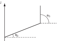
Figure 2.5.1 Angles used in determination of side shell pressure for planing
craft, P
dIs
5.3 Impact pressure for craft with foils and lifting devices
5.3.2 The bottom
impact pressure, is given by the greater of P
fba or P
fbb, where:
where
|
K
po
|
= |
longitudinal distribution factor |
| = |
1,0 between the aft end of the L
WL and 0,75L
WL
|
| = |
2,0 at L
WL from the
aft end of L
WL, intermediate values to be
determined by linear interpolation
|
|
H
0
|
= |
operational height of craft, in metres, measured from the waterline
to the top of the keel at LCG |
|
H
03
|
= |
surviving waveheight as defined in Pt 5, Ch 2, 2.1 Parameters to be used for the determination of load and design criteria 2.1.15 but is not taken as less than 1,0
|
|
L
WL
|
= |
waterline length, in metres, see
Pt 5, Ch 2, 2.1 Parameters to be used for the determination of load and design criteria 2.1.19
|
|
V
|
= |
allowable
speed in knots, see
Pt 5, Ch 2, 2.1 Parameters to be used for the determination of load and design criteria 2.1.2
|
P
fbb is not taken as less than zero.
V
R is the relative vertical speed of
the craft at impact, in knots. If this value is unknown, then the
following equation is to be used:
5.3.3 The side
shell impact pressure shall be taken as P
fb at
the chine or at the operating waterline for round bilge hullforms
as appropriate reducing to 0,3P
fb at the weather
deck. Intermediate values between the weather deck at side and the
chine or operating waterline, as appropriate, to be determined by
linear interpolation.
5.4 Forebody impact pressure for displacement mode
5.4.1 Forebody
and bow slamming pressure, P
f, at the load
waterline due to relative motion is to be taken as:
|
P
f
|
= |
f
f
L
WL (0,8 +
0,15Γ)2 kN/m2 at FP
|
| = |
P
dh at 0,9L
WL from aft end of L
WL
|
| = |
P
m at 0,75L
WL from aft end of L
WL
|
| = |
0,0 between aft end of L
WL and
0,75L
WL from aft end of L
WL
|
Intermediate values to be determined by linear interpolation.
Table 2.5.2 Forebody impact pressure
factor
| Craft type
|
f
f
|
| Mono-hull craft in non-displacement
mode
|
0,94
|
| Mono-hull craft in displacement
mode
|
0,89
|
| Catamarans and multi-hull craft with
partially submerged hulls
|
1,0
|
| Swaths and multi-hull craft with
fully submerged hulls
|
0,91
|
| Craft supported by hydrodynamic lift
provided by foils or other lifting devices
|
0,81
|
Note Where multiple craft types apply, the higher value of
f
f is to be used.
|
5.4.2 The side
shell impact pressure shall be taken as P
f at
the chine or at the operating waterline for round bilge hullforms
as appropriate reducing to 0,4P
f at the weather
deck. Intermediate values between the weather deck at side and the
chine or operating waterline, as appropriate, are to be determined
by linear interpolation.
5.5 Forebody impact pressure for non-displacement mode
5.5.1 Forebody and bow slamming pressure, P
f, at the load waterline due to relative motion is to be taken as:
|
P
f
|
= |
the greater of P
dIs or f
f
L
WL (0,8 + 0,15Γ)2 kN/m2 at FP |
| = |
P
dIs at 0,75L
WL from aft end of L
WL
|
| = |
P
m at < 0,5L
WL from aft end of L
WL
|
| = |
0,0 between aft end of L
WL and 0,5L
WL from aft end of L
WL
|
Intermediate values to be determined by linear interpolation.
5.5.2 The side
shell impact pressure shall be taken as P
f at
the chine or at the operating waterline for round bilge hullforms
as appropriate reducing to 0,3P
f at the weather
deck. Intermediate values between the weather deck at side and the
chine or operating waterline, as appropriate, are to be determined
by linear interpretation.
|